
Echo suppressing method and apparatus

a suppression method and echo technology, applied in the direction of cross-talk reduction, line-transmission details, instruments, etc., can solve the problems of large amount of distortion contained in the sound, limiting the suppression of echo to approximately 20 db, and becoming difficult to have a conversation, so as to achieve the effect of reducing the amount of computation and facilitating the suppression of echo

Active Publication Date: 2014-08-19
NEC CORP
View PDF10 Cites 0 Cited by
  • Summary
  • Abstract
  • Description
  • Claims
  • Application Information

AI Technical Summary

Benefits of technology

This approach allows for efficient echo suppression without being affected by near-end noise and reduces computational complexity, effectively removing echoes even in environments with significant distortion and noise.

Problems solved by technology

In particular, when the near-end signal contains a large far-end audio signal component, delayed far-end audio is audible as an echo to the far-end speaker, so that it becomes difficult to have a conversation.
However, in an actual apparatus, a loudspeaker, for example, has a large nonlinear element.
In particular, when a small-sized loudspeaker used in a mobile phone or the like produces sound at high-volume levels, a large amount of distortion contained in the sound limits the suppression of the echo to approximately 20 dB.
In this case, the echo is transmitted as the near-end signal and is audible to the far-end speaker, so that it becomes difficult to have a conversation.
The echo suppressing apparatus of the third example of related art, however, requires a large amount of computation because of a complicated process for estimating the amount of echo crosstalk.
In particular, it requires a large amount of division operation.
Further, since the echo suppressing apparatus of the third example of related art uses the speech detection result indicative of whether or not the output signal of the microphone contains near-end audio, a wrong speech detection result increases the error in the amount of estimated echo crosstalk, so that the corrected first signal, which is corrected based on the estimation result, will be degraded.
That is, the echo will not be sufficiently suppressed, or the near-end audio will contain a large amount of distortion.
In particular, when the echo suppressing apparatus is used in an environment in which near-end audio along with high-level noise (near-end noise) is inputted, the error in the speech detection result likely increases, so that the echo will not be sufficiently suppressed, or the near-end audio will contain a large amount of distortion.

Method used


Image

  • Echo suppressing method and apparatus
  • Echo suppressing method and apparatus
  • Echo suppressing method and apparatus

Examples


first exemplary embodiment

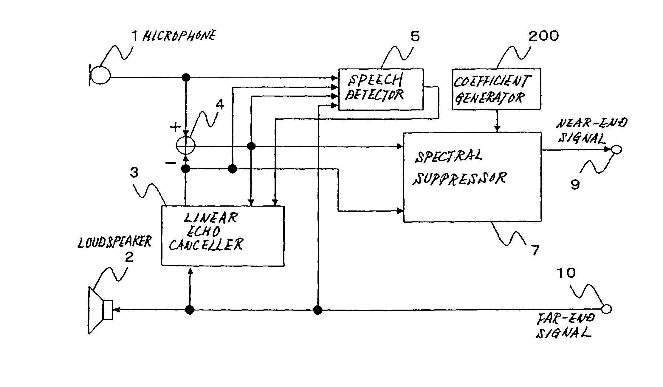
[0095]FIG. 8 is a block diagram showing the configuration of a first exemplary embodiment of the echo suppressing apparatus according to the present invention.

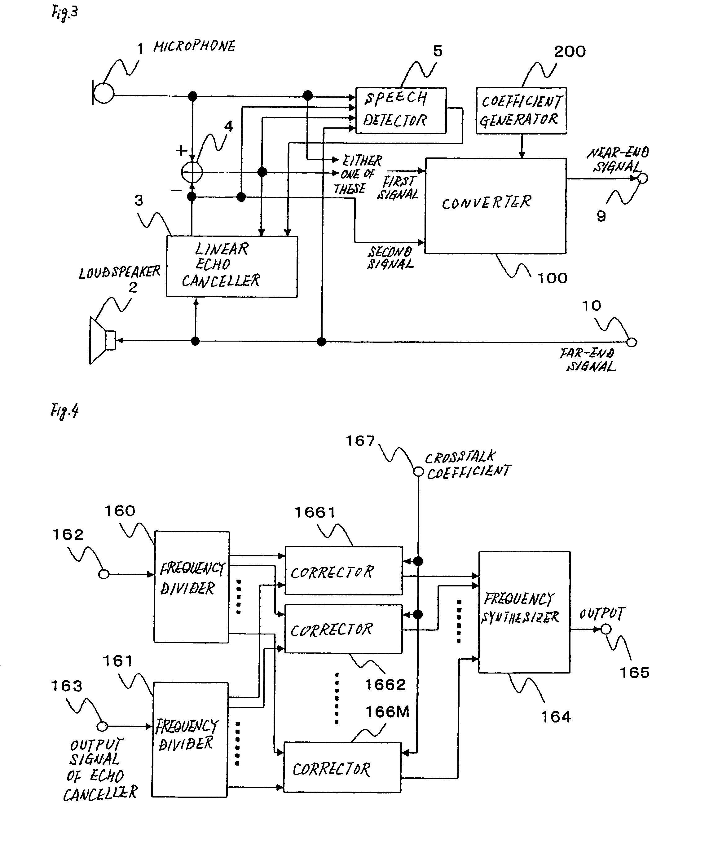
[0096]In the echo suppressing apparatus of the first exemplary embodiment, spectral subtractor 6 is used as converter 100 shown in FIG. 3.

[0097]Coefficient generator 200 in the first exemplary embodiment generates a crosstalk coefficient indicative of the amount of echo crosstalk that is occurring due to acoustic coupling between microphone 1 and loudspeaker 2 as described above.

[0098]Spectral subtractor 6 receives the output signal of subtractor 4, the output signal of linear echo canceller 3, the crosstalk coefficient generated in coefficient generator 200, and the speech detection result from speech detector 5.

[0099]Spectral subtractor 6 divides the output signal of subtractor 4 and the output signal of linear echo canceller 3 into signals in respective predetermined frequency ranges, and removes echoes from the signal comp...

second exemplary embodiment

[0154]FIG. 13 is a block diagram showing the configuration of a second exemplary embodiment of the echo suppressing apparatus according to the present invention.

[0155]The echo suppressing apparatus of the second exemplary embodiment differs from the echo suppressing apparatus of the first exemplary embodiment in that spectral subtractor 6 receives the output signal of microphone 1 instead of the output signal of subtractor 4.

[0156]In the echo suppressing apparatus of the first exemplary embodiment, linear echo canceller 3 removes the primary component of the echo, whereas in the echo suppressing apparatus of the second exemplary embodiment, spectral subtractor 6 removes the primary component of the echo. Except for the above configuration and operation, the second exemplary embodiment is the same as the first exemplary embodiment, and the removal of the echo resulting from distortion is advantageously carried out as in the first exemplary embodiment.

[0157]Therefore, in the echo supp...

third exemplary embodiment

[0160]FIG. 14 is a block diagram showing the configuration of a third exemplary embodiment of the echo suppressing apparatus according to the present invention.

[0161]The echo suppressing apparatus of the third exemplary embodiment differs from the echo suppressing apparatus of the first exemplary embodiment in that spectral subtractor 6 shown in FIG. 8 is replaced with spectral suppressor 7. Except the above configuration and operation, the third exemplary embodiment is the same as the first exemplary embodiment. A detailed description of the common portions will therefore be omitted.

[0162]Spectral suppressor 7 shown in FIG. 14 will be described below with reference to the corresponding Figs.

[0163]FIG. 15 is a block diagram showing an exemplary configuration of the spectral suppressor shown in FIG. 14.

[0164]As shown in FIG. 15, spectral suppressor 7 includes Fourier transformers 70 and 71, Fourier coefficient multipliers 76m (m=1 to M), and inverse Fourier transformer 74.

[0165]Fouri...


PUM


Abstract

Coefficient generator generates a crosstalk coefficient that is a predetermined value and that is used to calculate the amount of crosstalk of an echo. Converter uses either the output signal of a sound pickup device or the signal obtained by subtracting the output signal of an echo canceller from the output signal of the sound pickup device as a first signal, corrects the first signal based on the crosstalk coefficient generated in coefficient generator, and produces a near-end signal obtained by removing the echo from the first signal.

Description

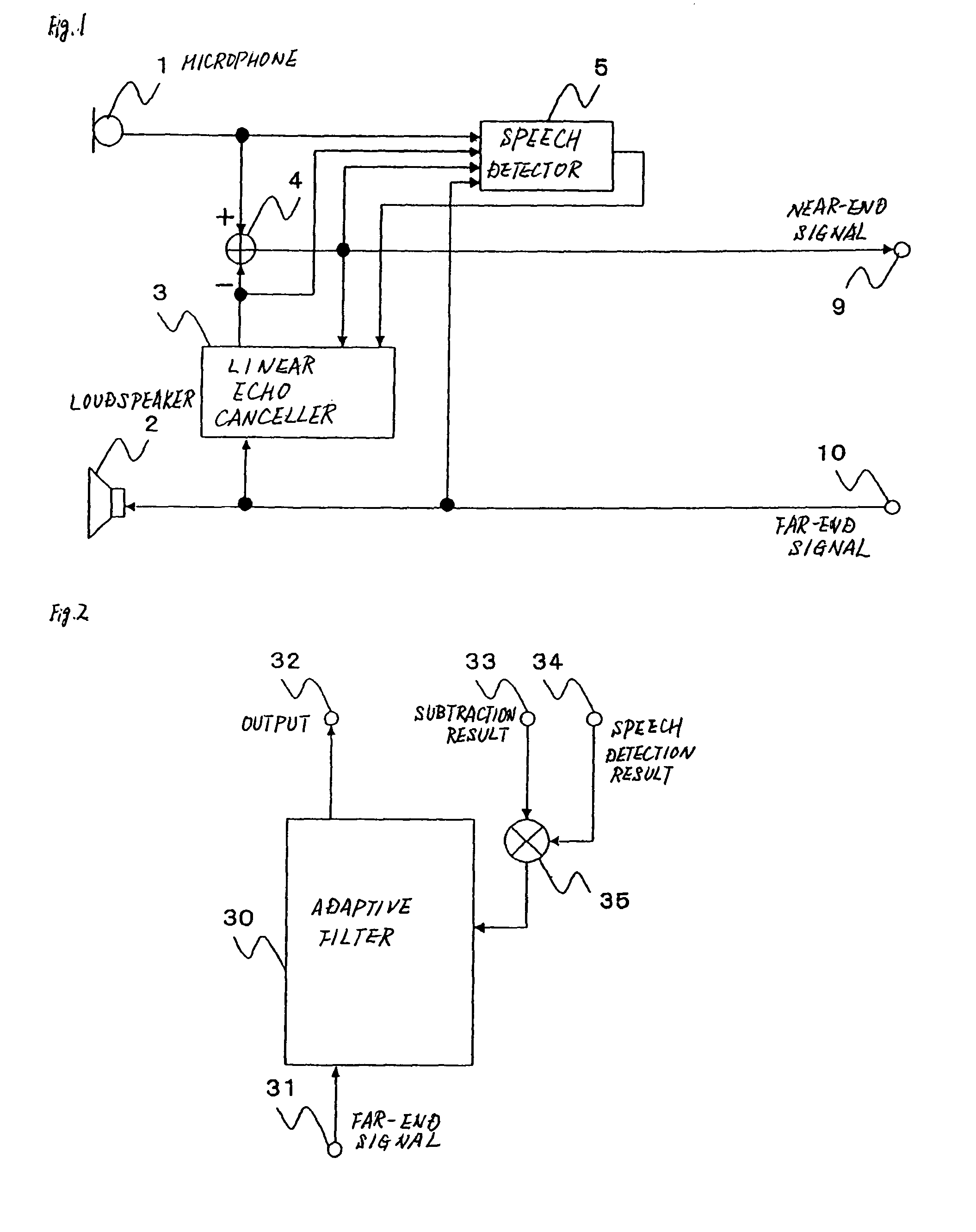
[0001]This application is the National Phase of PCT / JP2006 / 321267, filed Oct. 25, 2006, which claims priority to Japanese Application No. 2005-311180, filed Oct. 26, 2005, the disclosures of which are hereby incorporated by reference in their entirety.TECHNICAL FIELD[0002]The present invention relates to an echo suppressing method and apparatus for suppressing an echo generated when a loudspeaker produces audio and a microphone picks up sound at the same time.BACKGROUND ART[0003]FIG. 1 is a block diagram showing the configuration of an echo suppressing apparatus of a first example of related art.[0004]FIG. 1 shows an exemplary configuration of an echo suppressing apparatus for suppressing an echo generated in a hands-free phone.[0005]In FIG. 1, an audio signal from the far-end speaker (hereinafter referred to as far-end signal) inputted to input terminal 10 is converted into far-end audio by loudspeaker 2. On the other hand, microphone 1 picks up, for example, the voice of the near-...

Claims


Application Information

Patent Timeline
Patent Type & Authority Patents(United States)
IPC IPC(8): H04B15/00H04B1/38G10L21/0232H04B3/23H04M1/60H04R3/02
CPCH04R3/02H04B3/32H04M9/082
Inventor HOSHUYAMA, OSAMU
Owner NEC CORP
Learn More