Energy storing device in which energy is stored through spring torsion

a technology of energy storage and spring torsion, which is applied in the direction of sustainable buildings, machines/engines, mechanical equipment, etc., can solve the problems of inability to meet the needs of use, inability to maintain, and inability to provide solar energy at night, so as to prevent the damage of the energy storage unit, increase the rotational speed, and increase the torsion

Inactive Publication Date: 2014-08-26
CHIO CHUY NAN
View PDF10 Cites 5 Cited by
  • Summary
  • Abstract
  • Description
  • Claims
  • Application Information

AI Technical Summary

Benefits of technology

[0010]A second object of the present invention is to provide an energy storing device that may maintain a steady energy output.
[0012]To reach the objects, the energy storing device of the present invention is disclosed. In the energy storing device of the present invention, energy from an energy generating unit is stored in the form of spring torsion and then is output in a steady manner. The energy storing device of the present invention comprises a plurality of cog-wheels, a plurality of torsion magnitude limiting units, a plurality of single-directional input bearings, a plurality of energy storing units and a plurality of speed increasing cog-wheels. A rotational energy source is connected with the cog-wheels, and the torsion magnitude and direction of input energy are limited by the torsion magnitude limiting units and single-directional input bearings, respectively. Then, the input energy is stored in the energy storing units through the compression of the springs. The energy in the form of the compression may be output through the speed increasing cog-wheels. If the torsion magnitude exceeds a pre-determined value of the torsion magnitude limiting units, the torsion magnitude limiting units would interrupt the input of the torsion by the way of idling to prevent the damage of the energy storing units. The single-directional input bearings only allow the single-directional passage of the torsion from each of the twisting force limiting units to the energy storing units, to prevent passage of the torsion in the opposite direction so as to protect the torsion magnitude limiting units and cog-wheels. Each of the energy storing units includes at least two end rotational disc portions, which are connected with each other co-axially. A leaf spring unit is provided between each pair of rotational disc portions, and one end of the leaf spring units is bent in an opposite direction (opposite to the winding direction of the leaf spring) and is retained in a retaining groove to increase its torsion. The speed increasing cog-wheels are connected with the output end rotational disc portions to increase the rotational speed, so as to output the energy. In addition, the energy storing units may be connected in series or in parallel to increase the efficiencies in energy storage and energy output.

Problems solved by technology

Moreover, the combustion or use of petroleum seriously impacts the environment.
In addition, they are not stable.
For examples, solar energy is not available at night.
Wind sometimes is strong and sometimes is weak, and thus, is not stable.
Hydropower may becomes unusable during dry seasons.
However, such an energy storing set has disadvantages.
Its biggest drawback is the insufficiency of spring torsion because of the conventional spiral springs used in the energy storing set.
Therefore, the efficiency of energy storage is quite low.
Another drawback is the single-directional input bearings because these bearings may be damaged easily if the magnitude of torsion that is input into the energy storing set becomes too great.
Therefore, such an energy storing set may be used for small-size energy sources and can not be used for large-size energy sources, such as a power plant.

Method used


Image

  • Energy storing device in which energy is stored through spring torsion
  • Energy storing device in which energy is stored through spring torsion
  • Energy storing device in which energy is stored through spring torsion

Examples


Embodiment Construction

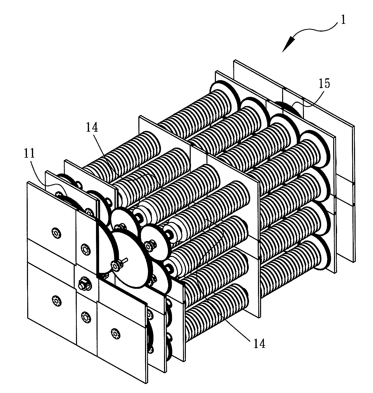
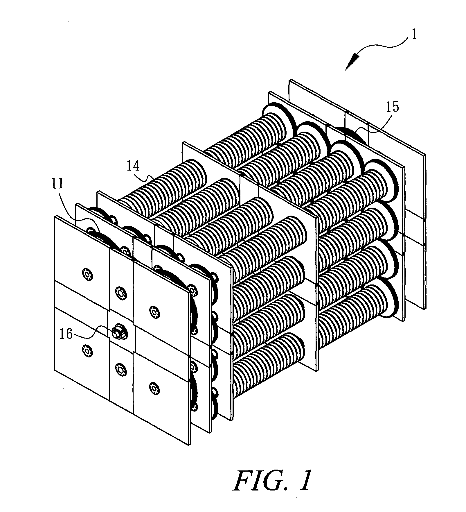
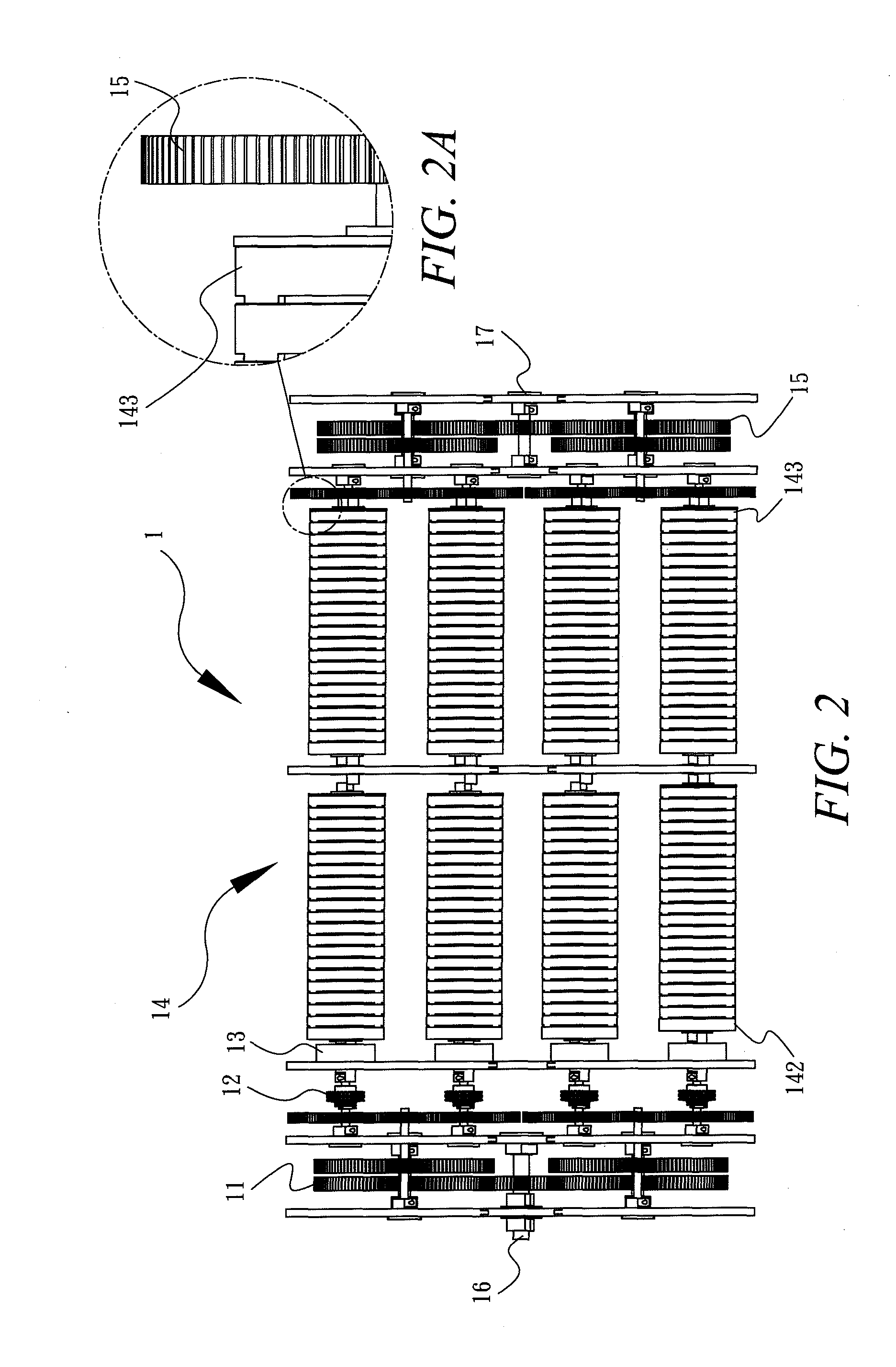
[0057]Please see FIGS. 1 to 3, which illustrate the energy storing device 1 of the present invention. The energy storing device 1 of the present invention comprises a plurality of cog-wheels 11, a plurality of torsion magnitude limiting units 12, a plurality of single-directional input bearings 13, a plurality of energy storing units 14 and a plurality of speed enhancing cog-wheels 15. An energy source is connected with the cog-wheels 11 and the torsion magnitude and direction of input energy are limited by the torsion magnitude limiting units 12 and single-directional input bearings 13, respectively. Then, the input energy is stored in the energy storing units 14 through spring torsion. The stored energy may be output through the speed enhancing cog-wheels 15.

[0058]In detail, first, when the energy is input, the torsion prompts the cog-wheels 11 to rotate. Then, if the magnitude of the torsion exceeds a pre-determined value of the torsion magnitude limiting units 12, the torsion ma...


PUM


Abstract

An energy storing device is disclosed. In the energy storing device of the present invention, energy from an energy generating unit is stored in the form of spring torsion and then is output steadily. The energy storing device of the present invention includes a plurality of cog-wheels, a plurality of torsion magnitude limiting units, a plurality of single-directional input bearings, a plurality of energy storing units and a plurality of speed enhancing cog-wheels. Each of the energy storing units includes at least two end rotational disc portions, which are connected with each other co-axially. A leaf spring unit is provided between each pair of rotational disc portions and one end of the leaf spring unit is bent in an opposite direction. In addition, the energy storing units may be connected in series or in parallel to increase the efficiencies in energy storage and energy output.

Description

BACKGROUND OF THE INVENTION[0001]1. Field of the Invention[0002]The invention generally relates to an energy storing device. More particularly, the invention relates to an energy storing device that may receive energy from various types of energy sources, store it through spring torsion and output it.[0003]2. Description of the Prior Art[0004]Because there is only a limited amount of petroleum available in the earth, it will definitely be used up some day in the future. In addition, the control and distribution of petroleum resources have been in the hands of a few countries. Moreover, the combustion or use of petroleum seriously impacts the environment. The development of new energy sources has been an important topic.[0005]In fact, there have been many types of green energy sources, such as solar energy, wind power, hydropower, etc., and these sources will remain available for a long time. However, these types of green energy sources have to be converted into a form that may be us...

Claims


Application Information

Patent Timeline
Patent Type & Authority Patents(United States)
IPC IPC(8): F16C1/00
CPCY02B10/30H02K7/18F03G1/08Y02E10/725F03G1/00F03G1/02Y02E10/72
Inventor CHIO, CHUY-NAN
Owner CHIO CHUY NAN
Why Eureka
Try Eureka