
Interference screw driver assembly and method of use

a screw driver and screw technology, applied in the field of interference screw driver, can solve the problems of cumbersome guide wire inserting, difficult grip, and insufficient attachment strength to withstand normal tensile loads, and achieve the effects of reducing the possibility of damaging surrounding tissue, and reducing the possibility of damage to surrounding tissu

Inactive Publication Date: 2014-08-26
THE LONNIE & SHANNON PAULOS TRUST AS AMENDED & RESTATED
View PDF19 Cites 8 Cited by
  • Summary
  • Abstract
  • Description
  • Claims
  • Application Information

AI Technical Summary

Benefits of technology

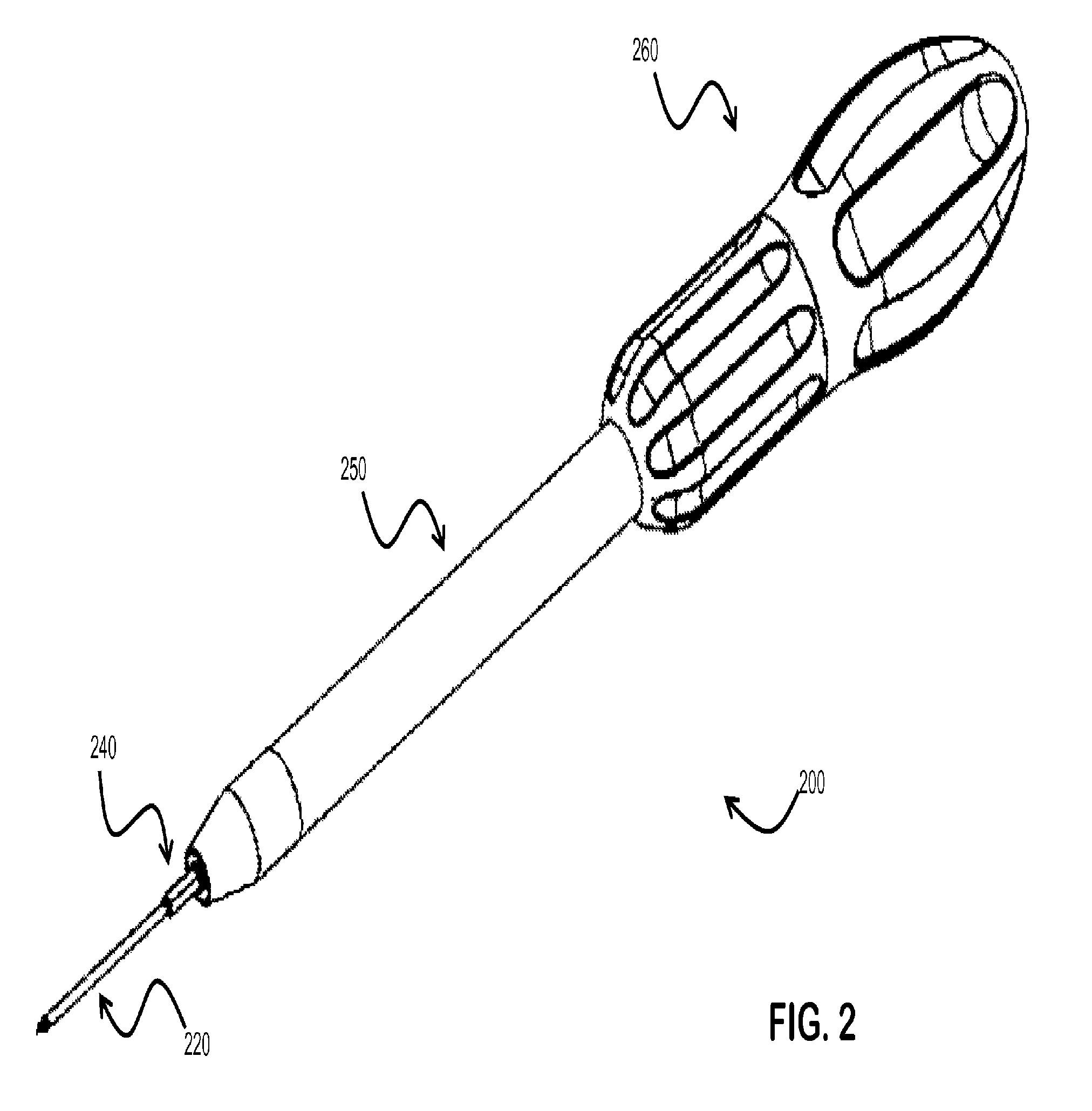
[0018]Embodiments of the disclosed assemblies and methods of use recognize that prior art angled surgical drivers are unsuitable for use in some surgeries where the procedures can benefit from the ability to put a larger amount, and a more direct, force behind the interference screw. Embodiments have the longitudinal axes of the assembly components being aligned, whereby a more direct force is able to be transferred from the handle of the assembly to the guide pin and the interference screw. This allows for more control of the assembly, ensures the proper engagement of the screw with the tissue and the bone and lowers the possibility of damaging surrounding tissue.
[0019]Embodiments also recognize that a rigid guide pin is able to advance with the screw, making the guide pin more difficult to bend or break than traditional guide wires.

Problems solved by technology

However, such methods often do not provide a sufficiently strong attachment to withstand the normal tensile loads to which they are subjected.
However, inserting the guide wire is cumbersome, because the wire is flexible, tends to bend and is difficult to grip.
Also, handling the guide wire and screw driver as separate pieces is inconvenient during surgery.

Method used


Image

  • Interference screw driver assembly and method of use
  • Interference screw driver assembly and method of use
  • Interference screw driver assembly and method of use

Examples


Embodiment Construction

[0032]An interference screw driver assembly and methods for use will now be described in detail with reference to the accompanying drawings. Although embodiments are described for the anchoring of devices and tissues to bone and other tissues, it is understood that the methods and systems described can be use for use in other medical attachment procedures. Notwithstanding the specific example embodiments set forth below, all such variations and modifications that would be envisioned by one of ordinary skill in the art are intended to fall within the scope of this disclosure.

Screw Driver Assembly:

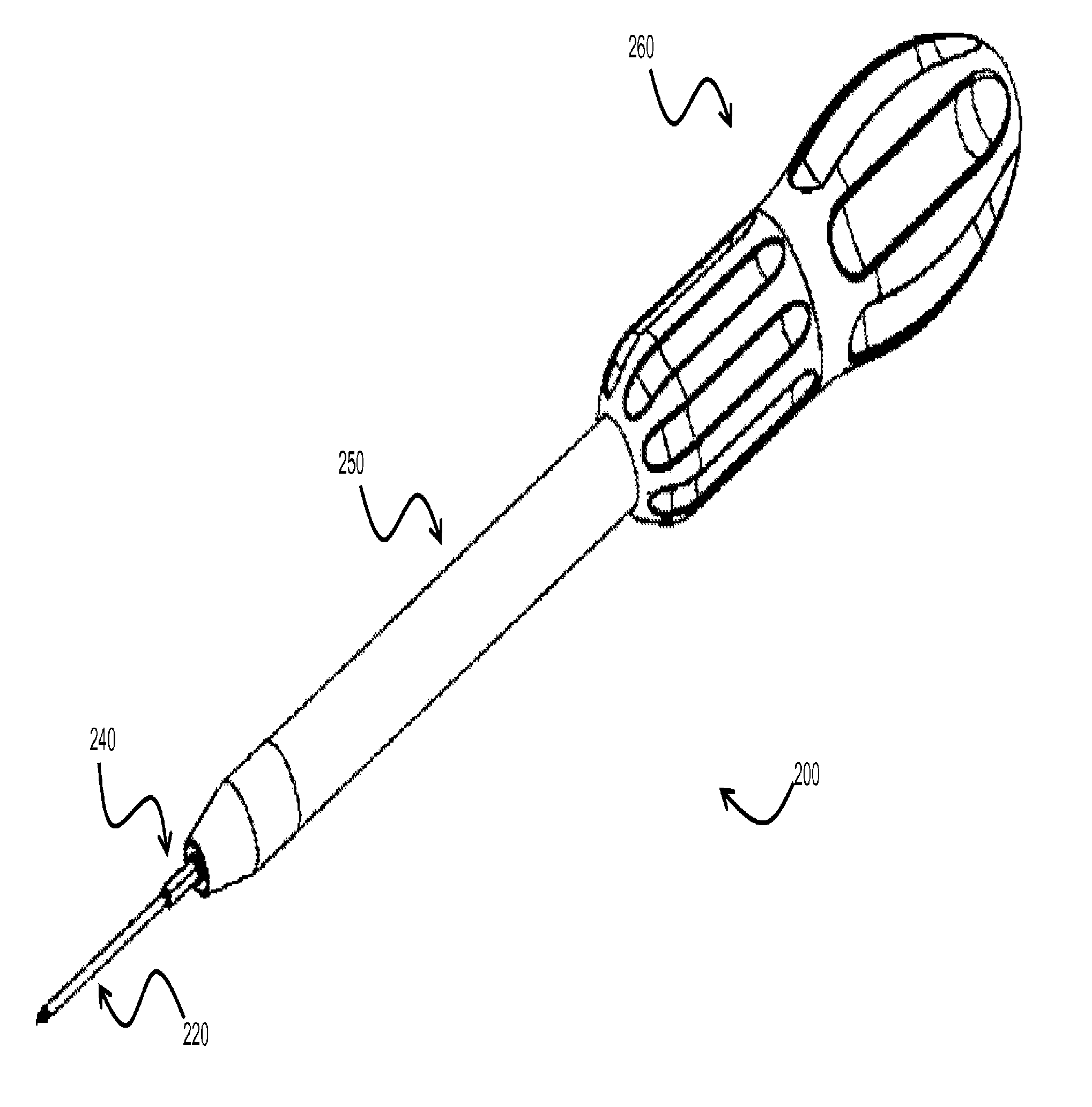
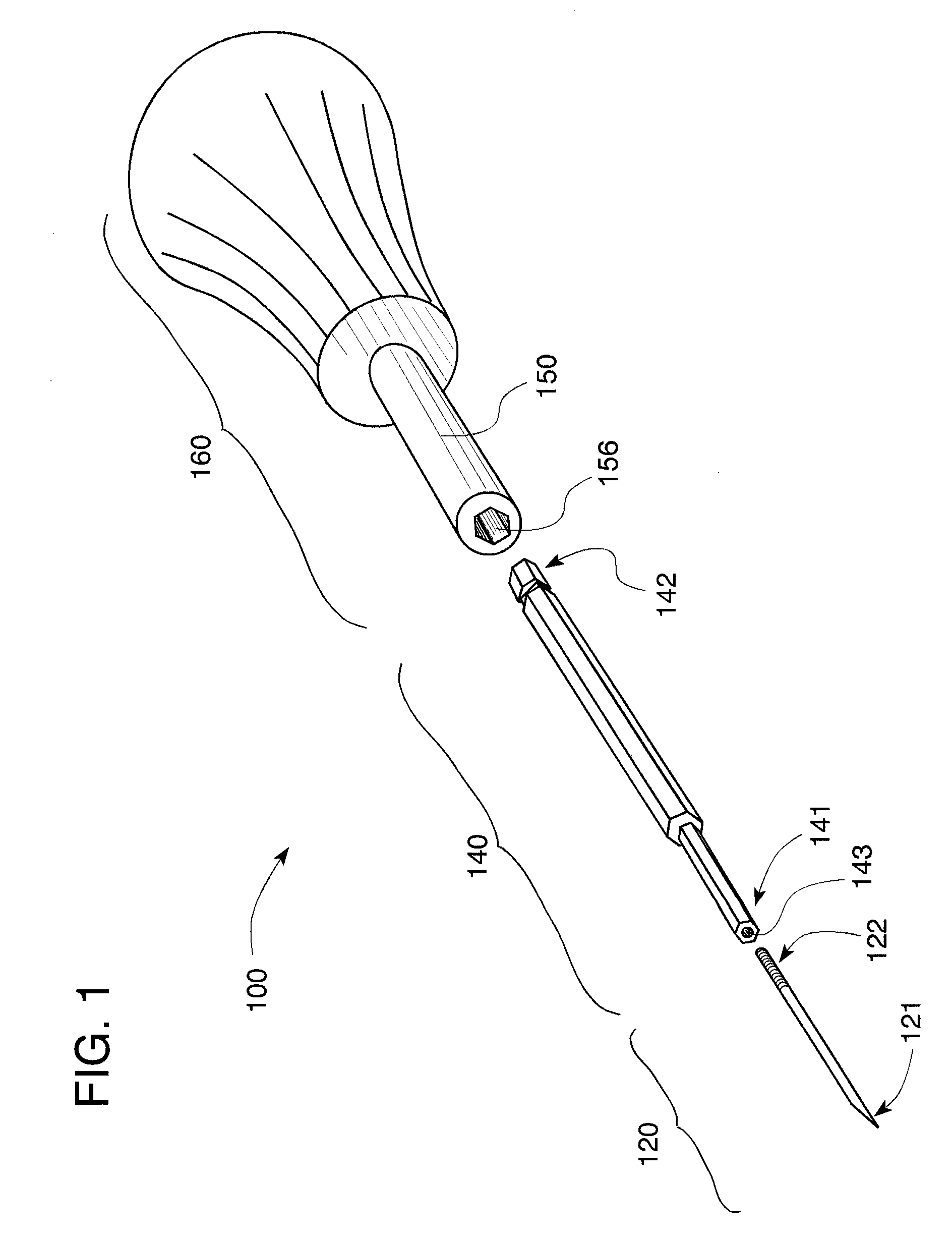
[0033]As shown in FIG. 1, one embodiment of the screw driver assembly 100 comprises a rigid guide pin 120, a driver 140 and a handle 160.

[0034]The rigid guide pin 120 is an elongated element made from a material such as titanium, stainless steel, nitinol or a nickel-titanium alloy wire. The guide pin can be of any length, but is typically on the order of 0.70-8 inches or more preferably 1-2....


PUM


Abstract

Embodiments of the present invention provide a cannulated screw driver assembly which includes a rigid guide pin such that the assembly can be used to assist the surgeon in inserting and positioning the rigid guide pin and an interference screw within a bone graft tunnel. Once the screw is properly placed, screw driver assembly components to include the rigid guide pin, the driver and the handle can be removed while the screw remains in the tunnel to secure the graft. In one embodiment, the interference screw can be removed from the distal end of the driver and the driver and handle can be removed from the screw's proximal end. Embodiments of the inventions also include an interchangeable driver to mate with different size and types of interference screws.

Description

CROSS-REFERENCE TO RELATED APPLICATIONS[0001]This application claims the benefit of the following provisional applications, each of which is hereby incorporated by reference in its entirety: U.S. Patent Application Ser. No. 61 / 041,222, entitled SELF-GUIDED CANNULATED SCREW DRIVER ASSEMBLY AND METHOD OF USE, filed on 31 Mar. 2008.STATEMENT REGARDING FEDERALLY SPONSORED RESEARCH OR DEVELOPMENT[0002]Not ApplicableREFERENCE TO SEQUENCE LISTING, A TABLE, OR A COMPUTER PROGRAM LISTING COMPACT DISC APPENDIX[0003]Not ApplicableBACKGROUND OF THE INVENTION[0004]The present invention relates to an interference screw driver for orthopedic surgery and, more specifically, to a self-guided screw driver which can be used with a rigid guide pin during fixation of a graft such as a ligament by insertion of an interference screw.Description of the Related Art[0005]In orthopedic surgery cannulated screws are used to attach plates, washers and other types of fixation devices to bone. They are also used ...

Claims


Application Information

Patent Timeline
Patent Type & Authority Patents(United States)
IPC IPC(8): A61F2/02A61B17/86A61B17/88A61F2/08B25B15/02B25B23/00
CPCB25B23/0042A61F2/0805B25B23/0035A61B17/8897B25B15/02A61B17/8645A61B17/8875
Inventor PAULOS, LONNIE
Owner THE LONNIE & SHANNON PAULOS TRUST AS AMENDED & RESTATED
Learn More