Inking Systems of a Printing Press and Method for Operating an Inking System

a printing press and inking system technology, applied in printing presses, printing press parts, printing, etc., to achieve the effect of improving the cost of inking units and/or ink transfer

Inactive Publication Date: 2008-07-10
KOENIG & BAUER AG
View PDF3 Cites 3 Cited by
  • Summary
  • Abstract
  • Description
  • Claims
  • Application Information

AI Technical Summary

Benefits of technology

[0008]The object of the present invention is to provide inking units for a printing press, which inking units are

Problems solved by technology

By acting unevenly upon two windings, which are arranged axially side by side,

Method used


Image

  • Inking Systems of a Printing Press and Method for Operating an Inking System
  • Inking Systems of a Printing Press and Method for Operating an Inking System
  • Inking Systems of a Printing Press and Method for Operating an Inking System

Examples


first embodiment

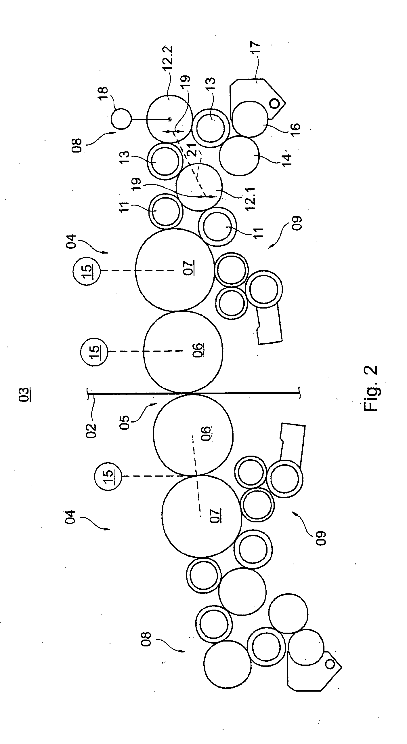
[0047]In the present invention, which is the simplest in terms of expenditure, the drive motor 18 is configured as an asynchronous motor 18, for which only one frequency, for example in print-off for the inking unit 08, and / or one electrical drive output or one torque, in print-on for the inking unit 08 is preset in an allocated drive control unit 46. When the inking unit 08 is in print-off, or in other words, when the application rollers 11 are out of rolling contact with the forme cylinder 07, the inking unit 08 can be placed in a circumferential speed that is suitable for the print-on position through use of the second distribution cylinder 12.2, using a preset frequency, at which speed the circumferential speeds of the forme cylinder 07 and of the application rollers 11 differ by less than 10%, and especially differ by less than 5%. This limit advantageously also applies as a condition for the print-on position in the embodiments which are set forth below. A preset frequency or ...

second embodiment

[0051]In a fourth preferred embodiment, a drive motor 18, and particularly a synchronous motor 18, is provided, which drive motor 18 is optionally speed-controlled in a first mode, for the inking unit 08 in print-off and in a second mode can be regulated with respect to torque, for the inking unit 08 in print-on. For speed control, the drive control unit 46 and the drive motor 18 preferably again have an inner control circuit, which, in a manner similar to that of the second embodiment, comprises a reset for an external angular sensor 47 or for a sensor system which is internal to the motor. When synchronous motors 18 are used, several such synchronous motors 18 in a printing unit 01 can be assigned a shared frequency transformer or converter.

[0052]A further improvement on the fourth preferred embodiment of the present invention, that is advantageous in terms of versatility, but which is more complicated, involves configuring the drive motor 18 as a servomotor 18 that can optionally...

fourth embodiment

[0053]In the case of a drive motor 18 that is implemented in the manner of the second, third, or especially the fourth embodiment, and which can be at least speed-synchronized, and especially can be speed-controlled, the drive control unit 46 is advantageously in signal connection with a so-called virtual control axis, in which an electronically generated control axis position F rotates. The rotating control axis position F serves in synchronization, with respect to the correct angular position and its temporal change, angular velocity F, in mechanically independent drive motors of units that are assigned to the same web, and especially drive motors of individual printing group cylinders or groups of printing group cylinders, and / or the drive of a folding unit. In the operating mode, in which the inking unit 08 is to be actuated in synchronization with respect to the speed of the forme cylinder 07, a signal connection with the virtual control axis can thus supply the information on ...


PUM


Abstract

An inking system of a printing press is utilized for inking a printing cylinder. The inking system is configured as a long roller inking system and includes two distributing cylinders that are disposed serially in a roller train. A first one of these distributing cylinders is mounted, in the roller train, close to the printing cylinder. The other of these distributing cylinders is mounted, again in the roller train, further away from the printing cylinder. The printing cylinder is rotationally force-driven by an angle position controlled drive motor. One of the two distributing cylinders of the inking system is rotationally force-driven by a drive motor that is mechanically independent of the drive for the printing cylinder. The other one of the two distributing cylinders is rotationally driven by frictional engagement with adjacent rollers or cylinders. It is thus configured without a mechanical drive connection to one of the drive motors other than the frictional engagement with the adjacent roller or cylinders which are intended to rotationally drive it.

Description

CROSS-REFERENCE TO RELATED APPLICATIONS[0001]This application is the U.S. National Phase, under 35 USC 371, of PCT / EP2006 / 050961, filed Feb. 15, 2006; published as WO 2006 / 100158 A2 and A3 on Sep. 28, 2006, and claiming priority to DE 10 2004 014 060.2, filed Mar. 23, 2005, the disclosures of which are expressly incorporated herein by reference.FIELD OF THE INVENTION[0002]The present invention is directed to inking units of a printing press and to methods for operating an inking unit. The inking unit is configured as a single train roller inking unit with two distribution cylinders that are arranged in series in the roller train. One distribution cylinder is close to or proximate the forme cylinder while the other is more distant or remote from the forme cylinder.BACKGROUND OF THE INVENTION[0003]In WO 03 / 039872 A1, an inking unit for a printing press is described. Two distribution cylinders of that inking unit are mechanically coupled to each other and are rotationally actuated via ...

Claims


Application Information

Patent Timeline
IPC IPC(8): B41F31/26
CPCB41P2213/734B41F31/004
Inventor SCHNEIDER, GEORGFISCHER, MICHAEL HEINZ
Owner KOENIG & BAUER AG
Why Eureka
Try Eureka