
System, method, and apparatus for planter weight transfer

a planter and weight technology, applied in the field of planter weight transfer, can solve the problems of inconvenient installation, increased weight and force on the extremities of the tool bar, and inconsistencies in the depth of the seed trough and the seed planting depth, and achieve the effect of simple installation

Pending Publication Date: 2020-11-12
MARTIN RONALD STEVE
View PDF1 Cites 2 Cited by
  • Summary
  • Abstract
  • Description
  • Claims
  • Application Information

AI Technical Summary

Benefits of technology

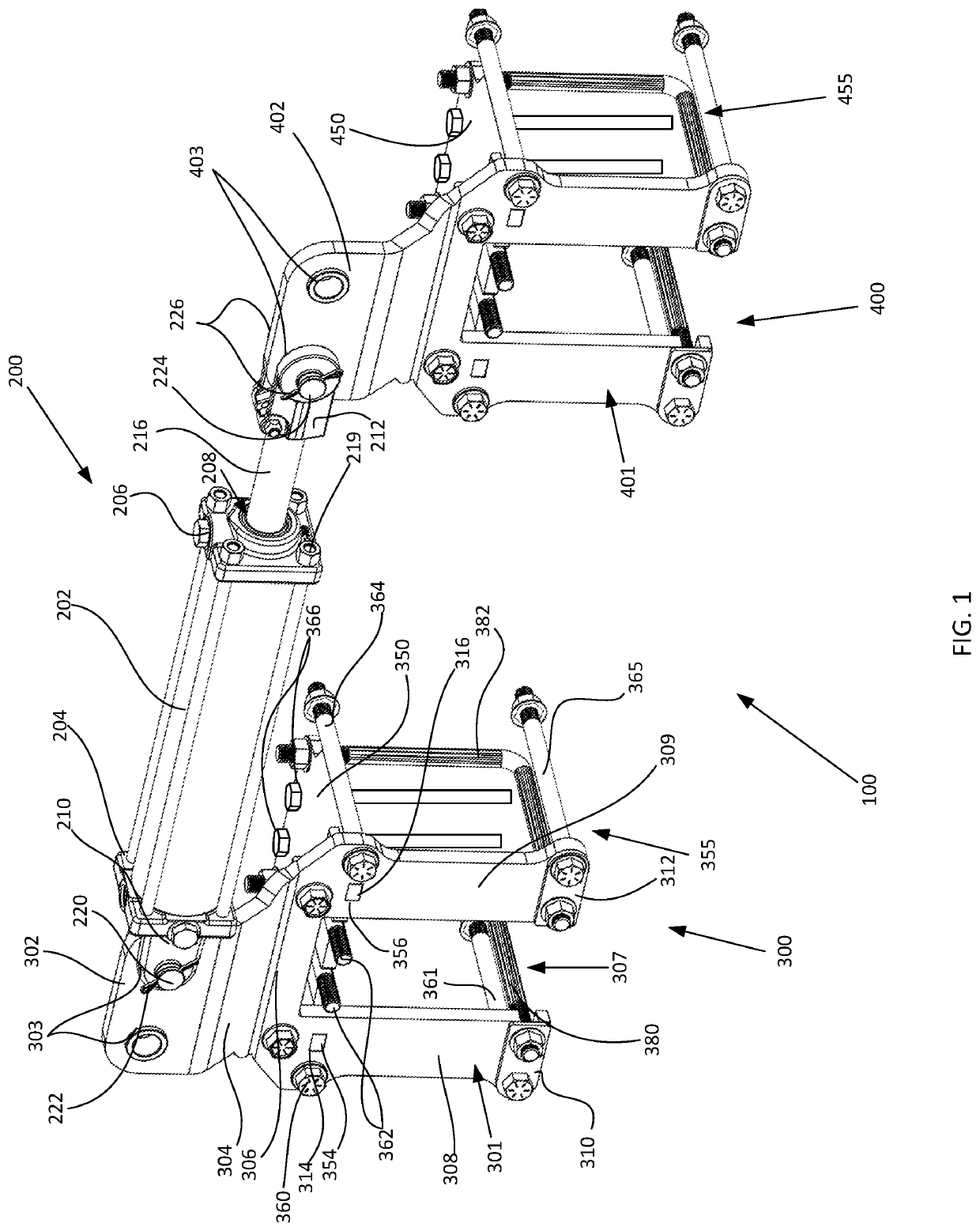
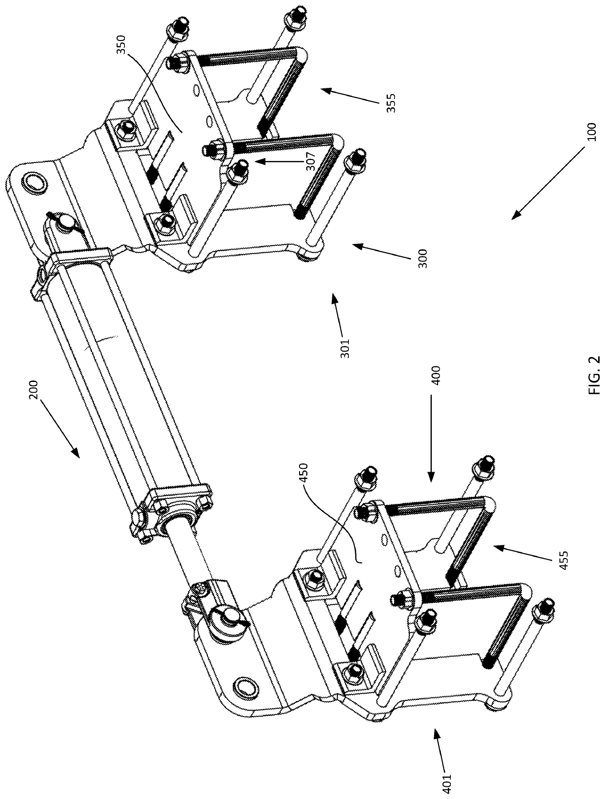
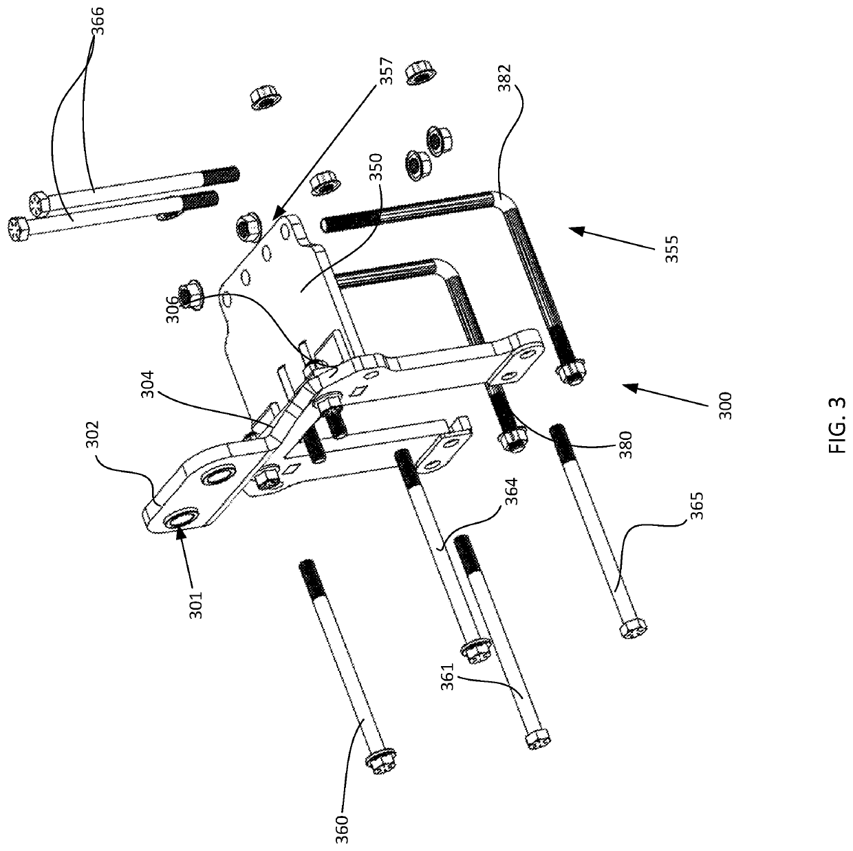
The present invention provides a bolt-on, removably installable, row planter tool bar weight transfer system that can be used with new or retrofit older row planter tool bars. The weight transfer system can adjust the weight transferred to the tool bar to ensure proper engagement with the soil for planting seeds at the proper depth. The weight transfer system is installable without requiring modification of the tool bar and distributes force on the tool bar and not on the fastening means used to secure the system. The technical effects of the invention are consistent and predictable seed emergence and growth characteristics across all planted rows regardless of the distance from the center of the planter on the tool bar and improved performance and durability of the weight transfer system.

Problems solved by technology

However, there are downsides to tillage that are driving modern farmers towards “low-till” or “no-till” farming systems.
As the number of planting rows is increased the weight and force exerted on the extremities of the tool bar is also increased because of the weight of the equipment needed for each planting row.
For a longer tool bar, an issue may occur when the weight at the center of the planter or tractor is significantly more than the weight at the ends of the wings or tool bars used with the planter.
The decreased weight on each planting apparatus, including at the row cleaner, planter, and row closer, at distances further from the tow bar or planter may cause inconsistencies in the depth of the seed trough and in the seed planting depth.
Excess weight at any point on the planter including at the planning apparatuses on the tool bar wings may cause compaction around the pinch rows between the tractor and the planter wheels.
In some circumstances, for example in uneven terrain, weight at the ends of the tool bar farthest from the drawbar may cause the angle of the various assemblies to not match those of assemblies closer to the drawbar.
However, existing systems and methods typically require plates, frames, or mounts to be welded directly onto the tool bar.
This type of installation method is difficult, time consuming, and is not easily removed.

Method used


Image

  • System, method, and apparatus  for planter weight transfer
  • System, method, and apparatus  for planter weight transfer
  • System, method, and apparatus  for planter weight transfer

Examples


Embodiment Construction

[0046]The present invention will now be described in more detail with reference to exemplary embodiments as shown in the accompanying drawings. While the present invention is described herein with reference to the exemplary embodiments, it should be understood that the present invention is not limited to such exemplary embodiments. Those possessing ordinary skill in the art and having access to the teachings herein will recognize additional implementations, modifications, and embodiments, as well as other applications for use of the invention, which are fully contemplated herein as within the scope of the present invention as disclosed and claimed herein, and with respect to which the present invention could be of significant utility.

[0047]The following discussion provides example embodiments of the inventive subject matter. Although each embodiment represents a single combination of inventive elements, the inventive subject matter is considered to include all possible combinations ...


PUM


Abstract

An removably installable apparatus and system for managing weight transfer along a tractor drawn tool bar for use in row planting systems is provided. The planter weight transfer system comprises first and second bolt-on bracket assemblies, each bolt-on bracket assembly comprising a primary plate and a secondary plate secured to each other and to a row planter tool bar by a set of fasteners. Additionally, the bolt-on brackets are joined at the top by an actuator which applies a force on the brackets.

Description

CROSS-REFERENCE TO RELATED APPLICATIONS[0001]The present invention claims benefit of priority to U.S. Provisional Pat. App. No. 62 / 844,377, entitled SYSTEM, METHOD, AND APPARATUS FOR PLANTER WEIGHT TRANSFER, filed May 7, 2019 (Martin), and to U.S. Provisional Pat. App. No. 62 / 696,535, entitled SYSTEM, METHOD, AND APPARATUS FOR PLANTER WEIGHT TRANSFER, filed Feb. 3, 2020 (Martin et al.), both of which are incorporated herein by reference in their entirety.FIELD OF THE INVENTION[0002]The present disclosure is generally applicable to the field of agricultural equipment, and more particularly for improved seed trough formation, seed planting, row closing, and row cleaning in no-till farming applications.AUTHORIZATION PURSUANT TO 37 C.F.R. § 1.171 (d)(c)[0003]A portion of the disclosure of this patent document contains material which is subject to copyright and trademark protection. The copyright owner has no objection to the facsimile reproduction by anyone of the patent document or the...

Claims


Application Information

Patent Timeline
IPC IPC(8): A01B63/00A01C7/00A01C5/00
CPCA01C7/00A01B63/004A01C5/00A01C7/205A01C7/208A01C7/08F16M13/022F16M2200/047A01B63/32A01B63/11
Inventor MARTIN, RONALD STEVE
Owner MARTIN RONALD STEVE
Learn More