Heating or cooling mat

a heating or cooling mat and mat technology, applied in the field of heating or cooling mats, can solve the problems disturbing the adhesive surface, and difficulty in using double-side adhesive tape, etc., and achieve the effect of poor bonding engagemen

Active Publication Date: 2014-08-26
DANFOSS AS
View PDF23 Cites 4 Cited by
  • Summary
  • Abstract
  • Description
  • Claims
  • Application Information

AI Technical Summary

Benefits of technology

[0009]Preferably, the heating and cooling unit is fixed on the carrying sheet by means of an adhesive strip adhering to the top side of the carrying sheet, the adhesive strip and the adhesive tape overlapping each other in the rolled up state of the heating or cooling mat. The adhesive strip is then used for two purposes. Firstly, it fixes the heating and cooling unit on the carrying sheet. Secondly, it forms the surface, on which the adhesive of the adhesive tape is fixed on the top side of the carrying sheet. Thus, the design and the properties of the top side of the carrying sheet are freer. The top side of the carrying sheet does not have to be designed so that the adhesive of the adhesive tape easily disengages from it. This property is merely required for the upper side of the adhesive strip.
[0011]Preferably, the heating and cooling unit has an electrical cable. An electrical cable is heated, when passed by an electrical current. This is particularly the case, when the electrical cable if formed as a resistance cable. By means of a suitable dimensioning of the resistance values, the predetermination of the heat output can be relatively accurate.
[0015]Preferably, the adhesive strip has a surface, which causes a substantially poorer bonding engagement with the adhesive on the bottom side of the adhesive tape than the bonding engagement of the adhesive of the adhesive strip with the top side of the carrying sheet. When unrolling the heating or cooling mat, the adhesive tape will disengage from the adhesive strip, whereas the adhesive strip will not disengage from the carrying sheet. A damaging of the heating or cooling mat when unrolling is thus reliably avoided.
[0016]It is also advantageous, when the upper side of the adhesive strip has a non-stick coating. A non-stick coating makes it possible for the adhesive tape to be removed from the upper side of the adhesive strip without problems. Remainders of the adhesive of the adhesive tape on the upper side of the adhesive strip are thus avoided. Also the force required for unrolling the heating or cooling mat is kept small.

Problems solved by technology

However, the use of a double-side adhesive tape is problematic, as a double-side adhesive tape will have an adhesive surface facing downwards, when fixed on the carrying sheet.
This adhesive surface would be disturbing during handling, so that usually the free side of a double-side adhesive tape is covered by a protective plastic sheeting.
If, however, this protective plastic sheeting would remain on the bottom side of the adhesive tape, the removal of this sheeting during installation of the heating or cooling mat would require substantial efforts.
Secondly, it forms the surface, on which the adhesive of the adhesive tape is fixed on the top side of the carrying sheet.

Method used


Image

  • Heating or cooling mat
  • Heating or cooling mat

Examples


Embodiment Construction

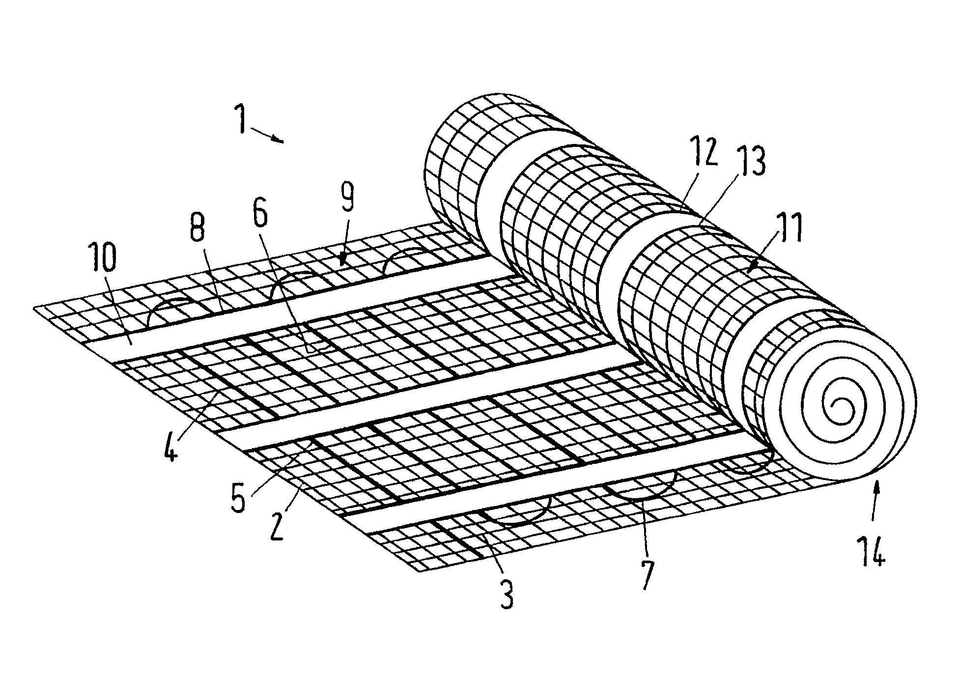
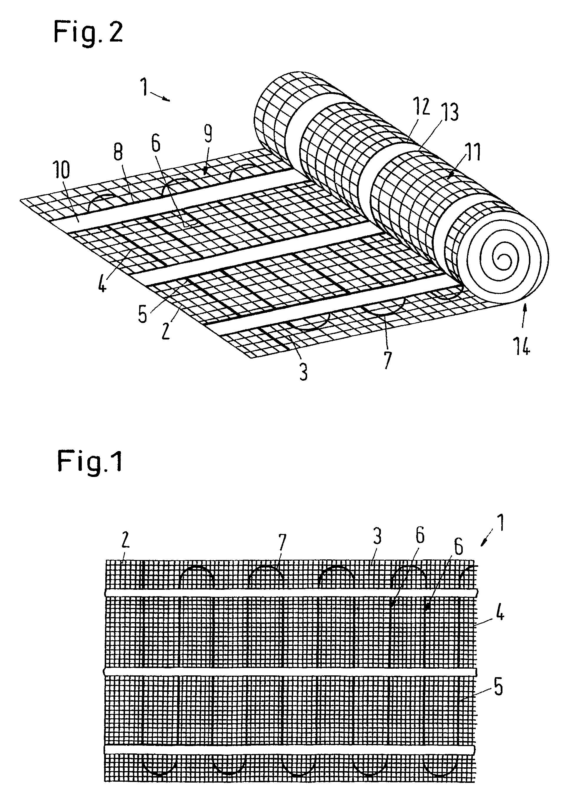
[0021]A heat conducting mat 1 has a carrying sheet 2 in the form of a grid. The carrying sheet 2 thus has longitudinal fibres 3, which extend in the longitudinal direction of the carrying sheet, and transverse fibres 4, which extend diagonally to the longitudinal direction. (In many cases, the longitudinal fibres 3 are also called warp and the transverse fibres 4 are also weft.

[0022]On the surface of the carrying sheet 2 visible in FIG. 1 is located a heating cable 5, which has a plurality of sections extending in parallel with the transverse fibres 4. These sections 6 are connected with each other by means of arched sections 7. In a manner not shown, an electrical current can be led through the heating cable 5 via terminals, which are also not shown, said current converting electrical energy into heat energy.

[0023]The heating cable 5 is fixed on the top side 9 of the carrying sheet 2 by means of three unilaterally bonding adhesive strips 8. This is easily realised in that after pla...


PUM


Abstract

The invention concerns a heating or cooling mat (1) with a carrying sheet (2) having a top side (9) and a bottom side (11), and at least one heating and cooling unit (5) located on the carrying sheet (2), an adhesive being located on the bottom side (11) of the carrying sheet (2). It is endeavored to improve the handling properties of the heating or cooling mat. For this purpose, the adhesive is located on a double-sided adhesive tape (12), which is fixed on the bottom side (11) of the carrying sheet (2), the adhesive on the bottom side of the adhesive tape (12) being covered by the top side of the carrying sheet (2) and the adhesive tape (12) bonding with the top side of the carrying sheet (2) in the rolled up state of the heating or cooling mat (1).

Description

CROSS REFERENCE TO RELATED APPLICATIONS[0001]This application is entitled to the benefit of and incorporates by reference essential subject matter disclosed in International Patent Application No. PCT / DK2006 / 000729 filed on Dec. 20, 2006 and German Patent Application No. 10 2005 061 784.0 filed Dec. 23, 2005.FIELD OF THE INVENTION[0002]The invention concerns a heating or cooling mat with a carrying sheet having a top side and a bottom side, and at least one heating and cooling unit located on the carrying sheet, an adhesive being located on the bottom side of the carrying sheet.BACKGROUND OF THE INVENTION[0003]Such a mat is, for example, known from EP 1 157 241 B1. The carrying sheet has the form of a grid, on which a heating cable is arranged in a snake shape, longitudinal sections of the heating cable extending in parallel with grid wires. The heating cable is fixed on the top side of the carrying sheet by means of a grid-shaped adhesive tape. An adhesive material is put onto the ...

Claims


Application Information

Patent Timeline
Patent Type & Authority Patents(United States)
IPC IPC(8): H05B1/00H05B3/34A47C21/04F24D3/14F24D13/02
CPCF24D3/141F24D13/02H05B3/342H05B2203/003H05B2203/014H05B2203/017Y02B30/26Y02B30/00
Inventor OLSEN, LEIFMELBALLE, THOMASBERNTH, TAJUTOFT, VERNER
Owner DANFOSS AS
Why Eureka
Try Eureka