Waveguide orthomode transducer

a transducer and waveguide technology, applied in the field of wave transmission lines, can solve the problems of limiting power handling, increasing insertion loss, and high manufacturing precision sensitivity, and achieve good performance

Active Publication Date: 2014-08-26
CENT NAT DETUD SPATIALES (CNES)
View PDF6 Cites 8 Cited by
  • Summary
  • Abstract
  • Description
  • Claims
  • Application Information

AI Technical Summary

Benefits of technology

[0020]The aim of the invention is to obtain a waveguide orthomode transducer which requires a low number of components and offers good performance, particularly in terms of power handling and higher order modes generation.
[0027]Used with a turnstile junction, the waveguide orthomode transducer of the invention has a high power handling threshold when compared to other state-of-art compact waveguide orthomode transducers.

Problems solved by technology

However cross-section reduction is known to limit power handling which is of great concern for telecommunication applications since the current trend is to increase the transmitted power per antenna.
This may result in increased insertion losses and higher sensitivity to manufacturing precision.

Method used


Image

  • Waveguide orthomode transducer
  • Waveguide orthomode transducer
  • Waveguide orthomode transducer

Examples


Embodiment Construction

Design of the Waveguide Orthomode Transducer

[0051]The Non-Conventional Use of the Turnstile Junction

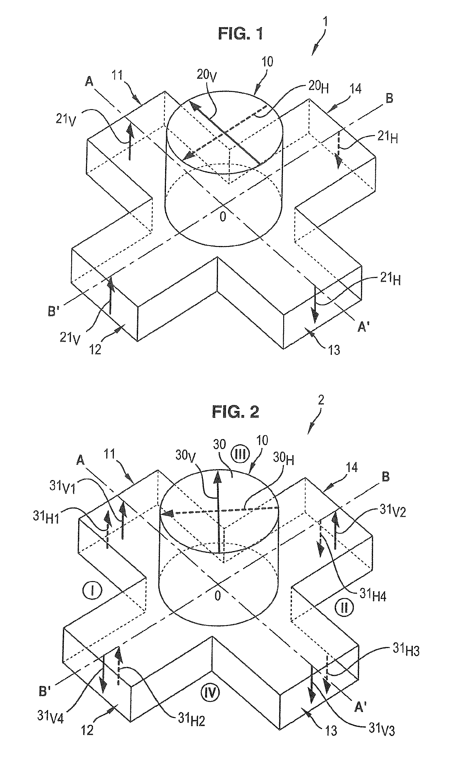
[0052]The waveguide orthomode transducer is based on a non-conventional use of the turnstile junction. In fact, the conventional turnstile junction can separate by itself two orthogonal polarizations, the complexity then comes from the combination network (see FIG. 1).

[0053]FIG. 2 illustrates the non-conventional use of the turnstile junction.

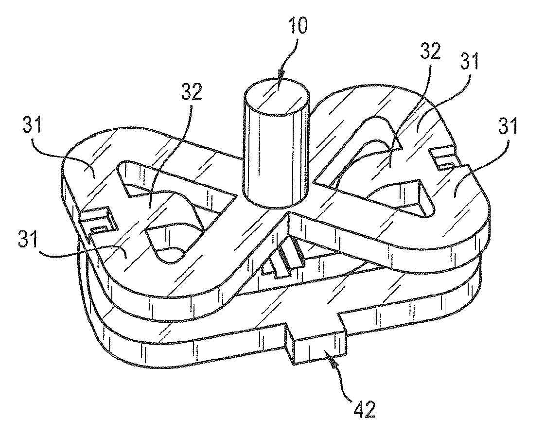
[0054]In order to reduce the complexity of the combination network without crossings, the conventional junction is 45 degrees rotated which means that the signal enters in the transducer by the main waveguide 10 according to an orientation of 45° relative to the main axis AA′, BB′ of the junction 2.

[0055]A consequence of such a rotation is that the two polarizations are present in the four auxiliary waveguides 11-14, and the power of the radio-frequency signal entering in the transducer is divided by four.

[0056]A radio-frequency signal including ...


PUM


Abstract

A waveguide orthomode transducer, comprises: a junction having a main waveguide and four auxiliary waveguides lying along the two orthogonal main axis of the junction and defining four quadrants; a combination network comprising: two magic tees, each having an E-port, two opposed common-ports, and a H-port; an H-plane tee junction having a Σ-port and two opposed common-ports; and an E-plane tee junction having a Δ-port and two opposed common-ports. Two auxiliary waveguides define a first quadrant are respectively connected to the common-ports of one of the magic tees and the two other secondary waveguides defining a second quadrant opposite to the first quadrant are connected to the common-ports of the other magic tee. The tee junctions are used to connect similar magic tee ports so that the transducer separates towards two different outputs two orthogonally polarized signals entering at the main waveguide. Reciprocally, two signals entering respectively in the Σ-port and the Δ-port of the tees junctions are combined with orthogonal polarizations in the main waveguide.

Description

CROSS REFERENCE TO RELATED APPLICATIONS[0001]The present application is a national phase entry under 35 USC §371 of International Application No. PCT / EP2010 / 051180, filed Feb. 1, 2010, which claims the benefit of and priority to European Patent Application No. 09305099.5, filed Feb. 2, 2009, the entire disclosures of which are incorporated herein by reference.FIELD OF THE INVENTION[0002]The invention relates to wave transmission lines used as feeding network for antennas and more particularly to a feeding network known as orthomode transducer used to combine / separate two orthogonal polarizations.BACKGROUND OF THE INVENTION[0003]Orthomode transducers (OMT) are of great interest in various applications as they enable to combine or separate two signals in orthogonal polarizations.[0004]In telecommunications, for instance, these components permit an efficient use of the available bandwidth. In radar applications, one may use these components to separate the transmitted and received sign...

Claims


Application Information

Patent Timeline
Patent Type & Authority Patents(United States)
IPC IPC(8): H01Q1/50
CPCH01P1/161
Inventor FONSECA, NELSON
Owner CENT NAT DETUD SPATIALES (CNES)
Why Eureka
Try Eureka