Process for producing an acoustic device having a controlled-bandgap phononic crystal structure

a technology of phononic crystal structure and acoustic device, which is applied in the manufacture/assembly of piezoelectric/electrostrictive devices, transducer types, electrical instruments, etc., can solve the problems of inability to produce perfect cylinders, surface wave losses in substrates, and the practical production of devices does not allow the production of dimensions of any size, so as to achieve the effect of wide frequency band gap

Inactive Publication Date: 2014-09-02
COMMISSARIAT A LENERGIE ATOMIQUE ET AUX ENERGIES ALTERNATIVES
View PDF3 Cites 9 Cited by
  • Summary
  • Abstract
  • Description
  • Claims
  • Application Information

AI Technical Summary

Benefits of technology

[0009]In this context, the present invention proposes a solution for controlling, or even widening, the frequency bandgaps obtained for phononic crystals. Indeed, the applicant has demonstrated that the bandgap width is greater for example for conical holes in comparison with cylindrical holes, thereby making it possible to obtain wider frequency bandgaps, while maintaining technologically achievable geometries and thus making it possible to envisage novel applications or fabrication cost reductions.

Problems solved by technology

The holes produced tend to be as cylindrical as possible, but it is well known that it is not technologically possible to produce perfect cylinders.
This angle leads to surface wave losses in the substrate, and therefore poses a problem.
This is because the practical production of devices does not allow dimensions of any size to be produced.
Reducing the size leads to complicating the technological steps, and consequently a cost increase.

Method used


Image

  • Process for producing an acoustic device having a controlled-bandgap phononic crystal structure
  • Process for producing an acoustic device having a controlled-bandgap phononic crystal structure
  • Process for producing an acoustic device having a controlled-bandgap phononic crystal structure

Examples


Embodiment Construction

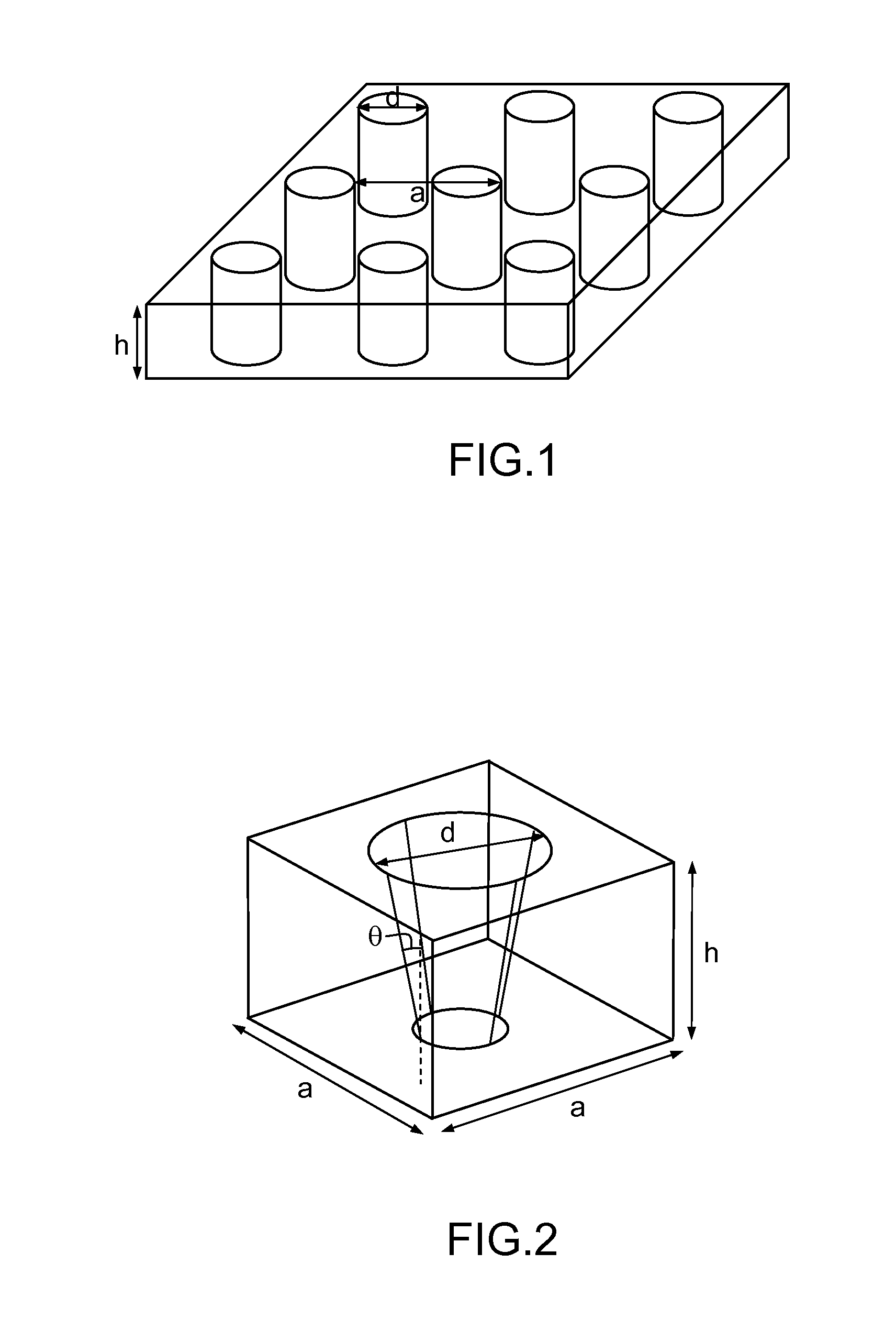
[0055]In general, the process of the present invention makes it possible to produce an acoustic device according to the invention having a preferably two-dimensional phononic structure comprising usually periodic features such that they enable the bandgaps of the phononic crystal structure to be controlled or even widened.

[0056]When a two-dimensional phononic crystal has a small thickness, of the same order of magnitude as the lattice parameter, it may also be called a structure having 2.5 dimensions.

[0057]The present invention may relate to structures on thin films composed of two different materials, but the principle is also applicable to more complex two-dimensional structures (bulk structures: phononic crystals on the surface of a substrate, or on a Bragg mirror, or structures having more than two materials). In all cases acoustic waves are involved, whether these be bulk waves (BAW) or plate waves (Lamb waves).

[0058]FIG. 2 illustrates an example of a periodic feature that may ...


PUM

PropertyMeasurementUnit
apex half-angleaaaaaaaaaa
thicknessaaaaaaaaaa

Abstract

A process for producing an acoustic device having a phononic crystal structure comprising inclusions produced in a first medium distributed in a matrix of a second medium, to block propagation of acoustic waves within a bandgap frequency band, includes: defining geometric parameters of said inclusions, which have walls contacting said matrix, making at least one non-zero first wall angle, to the normal of the plane of said structure, said geometric parameters including said first wall angle; determining a function relating to variation in frequency position of said bandgap with said wall angle or relating to variation in width of said bandgap with said wall angle; determining said at least first angle, for a selected frequency position and / or selected width of the bandgap, from the function or functions determined beforehand; and producing said inclusions having at least said first wall angle in said matrix formed by said second medium.

Description

CROSS-REFERENCE TO RELATED APPLICATION[0001]This application claims priority to foreign French patent application No. FR 1151101, filed on Feb. 11, 2011, the disclosure of which is incorporated by reference in its entirety.FIELD OF THE INVENTION[0002]The field of the invention is that of acoustic devices that operate by propagation of acoustic waves being blocked by a generally periodic organization of acoustically different materials for the purpose of providing electrical filter functions.BACKGROUND[0003]The term “acoustic device” is understood to mean any structure using acoustic wave propagation and notably acoustic filters or resonators.[0004]Such devices have operating frequencies that may range from a few Hz to a few GHz. The potential applications of these devices may be as acoustic lenses and RF filters, which may be used in wireless communication and notably in mobile telephony, or else as many anti-vibration or RF devices.[0005]According to the known art, as described not...

Claims


Application Information

Patent Timeline
Patent Type & Authority Patents(United States)
IPC IPC(8): H01L41/22
CPCH03H9/02653H01L21/0337H03H3/0072H03H3/08H03H9/02118H03H9/02125H03H9/02338H03H9/02866H03H9/172H03H9/6409Y10T29/42Y10T29/49002Y10T29/49005Y10T29/49007
Inventor GORISSE, MARIEREINHARDT, ALEXANDRE
Owner COMMISSARIAT A LENERGIE ATOMIQUE ET AUX ENERGIES ALTERNATIVES
Why Eureka
Try Eureka