Magnetic antenna and board mounted with the same

a technology of magnetized antenna and wound wire, which is applied in the field of magnetized antenna, can solve the problems of antenna applied thereto which has a coil of wound wire and is not suitable for mass production, and achieves the effects of low production cost, stable joining, and low variation

Active Publication Date: 2011-12-06
TODA IND
View PDF24 Cites 5 Cited by
  • Summary
  • Abstract
  • Description
  • Claims
  • Application Information

AI Technical Summary

Benefits of technology

According to a magnetic antenna of the present invention, since a conductive layer is provided by an LTCC technology, the laminated layers can be closely bonded to each other and the coil and the conductive layer can be stably joined together. In addition, it is not required to adjust a frequency of the magnetic antenna under environmental conditions upon use, and the frequency can be adjusted independently. Moreover, since the conductive layer is provided, the antenna does not undergo a change in characteristics even when brought close to a metallic object. Further, since a plurality of elements can be stably produced from one sheet, a large number of elements can be produced with little variation and at low production costs.
In particular, since the magnetic antenna according to the first to third aspects of the present invention undergoes as small a change in resonant frequency as 1 MHz or less when attached to a metal surface, it can be used in a wide frequency from 125 KHz to 2.45 GHz. For example, when the magnetic antenna is used in a 13.56 MHz RFID tag, a communication distance of 3 cm or greater can be achieved even when the tag is adhered to a metal surface. Also, when the antenna has a symmetrical green sheet laminated structure with respect to the coil at the center, a warpage of 0.5 mm or less per 1 cm length along the long side thereof after firing can be achieved. Therefore, the antenna is suitable for practical use.
In addition, since the magnetic antenna according to the fourth to seventh aspects of the present invention has a magnetic layer on the outside of the conductive layer, the change in characteristics at a time when adhered to a metallic object can be further decreased. The magnetic antenna of the present invention can be used in an RFID tag as well as an RFID tag reader / writer, and can be used in a wide frequency range from 125 kHz to 2.45 GHz when the magnetic layer for the coil is properly selected.

Problems solved by technology

The above magnetic antenna for use in an RFID tag, however, has the problem that when the wound coil is brought into contact with a metallic object, the contact surfaces between the wound wire and the metal plate become unstable to cause variations in characteristics of the antenna.
In any of an RFID tag and a reader / writer, an antenna applied thereto which has a coil of a wound wire is not suitable for mass-production.

Method used


Image

  • Magnetic antenna and board mounted with the same
  • Magnetic antenna and board mounted with the same
  • Magnetic antenna and board mounted with the same

Examples


example 1

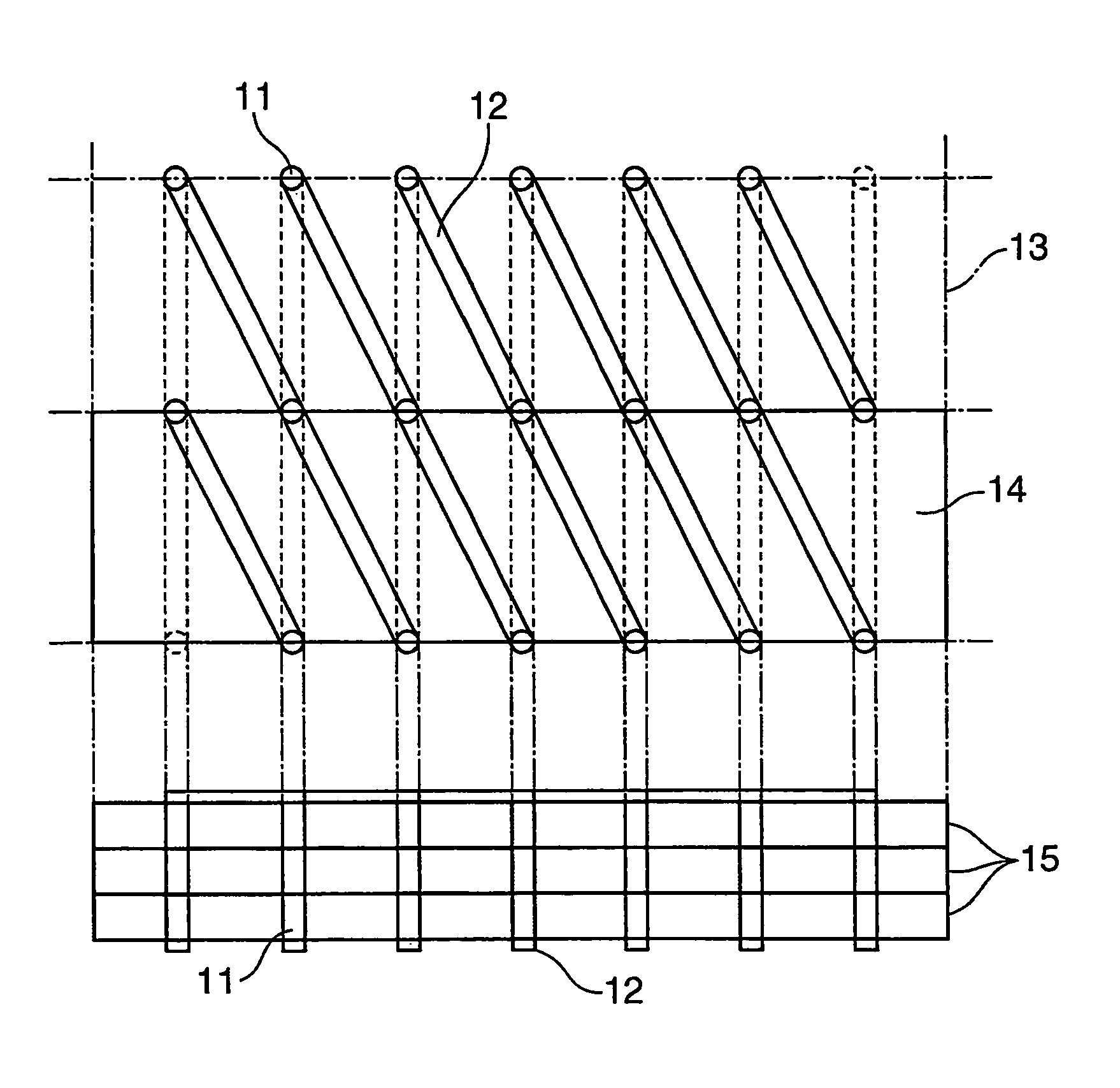
A magnetic antenna of the present invention was produced using an LTCC technology. First, a magnetic layer 15 was prepared. 100 Parts by weight of a calcined Ni—Zn—Cu ferrite powder which had been found to have a magnetic permeability of 100 at 13.56 MHz upon calcination at 900° C. (Fe2O3: 48.5 mol %, NiO: 25 mol %, ZnO: 16 mol %, CuO: 10.5 mol %), 8 parts by weight of a butyral resin, 5 parts by weight of a plasticizer, and 80 parts by weight of a solvent were mixed in a ball mill to prepare a slurry. The slurry was applied on PET films with a size of 150 mm×150 mm by a doctor blade to such a thickness that the resulting layer thickness after calcination would be 0.1 mm.

Insulating layers 16 were prepared as follows. 100 Parts by weight of a calcined Zn—Cu ferrite powder (Fe2O3: 48.5 mol %, ZnO: 41 mol %, CuO: 10.5 mol %), 8 parts by weight of a butyral resin, 5 parts by weight of a plasticizer, and 80 parts by weight of a solvent were mixed in a ball mill to prepare a slurry. The s...

example 2

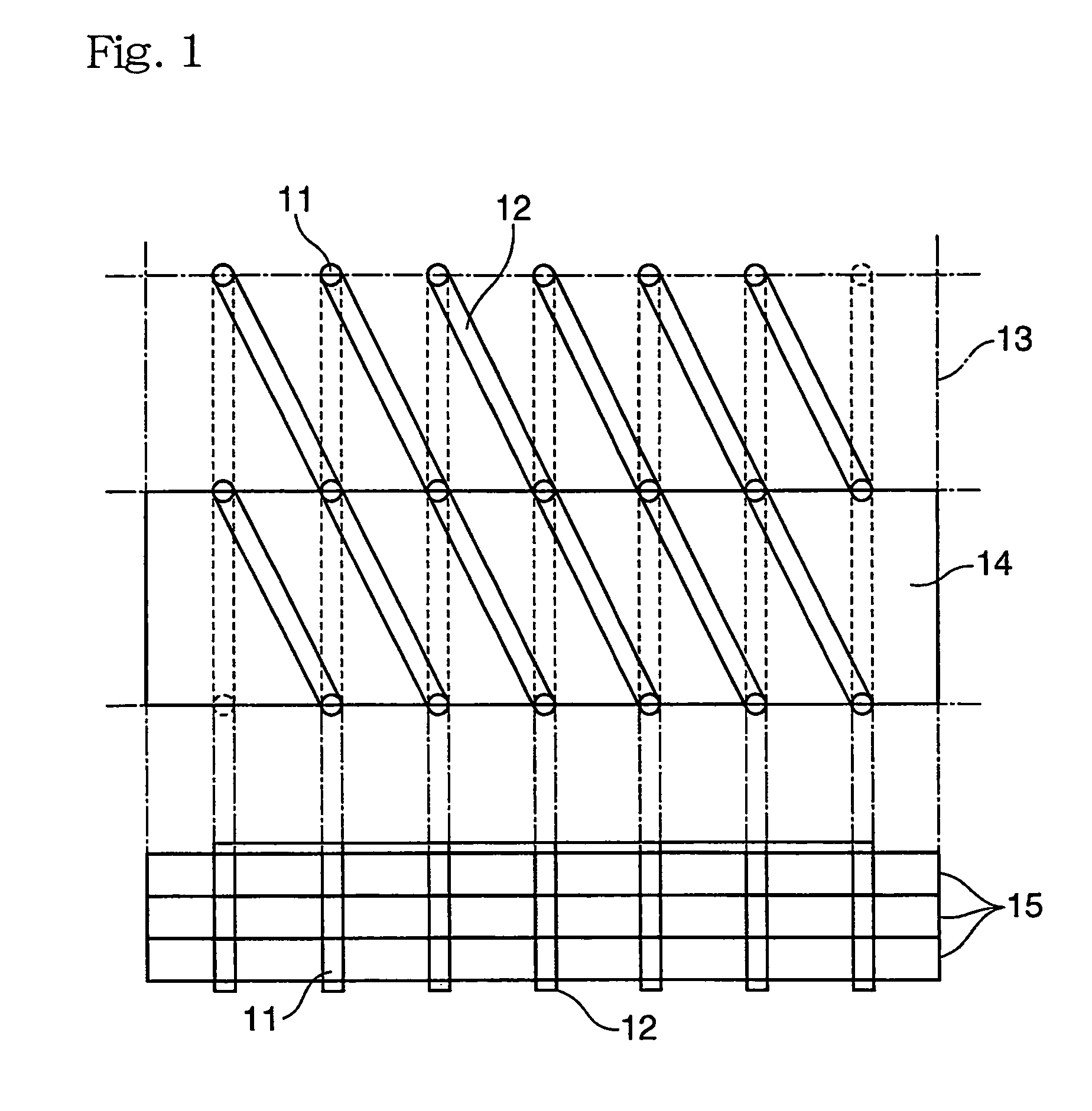
The same green sheets for the magnetic layer 15 as in Example 1, and green sheets comprising a glass ceramic, instead of a Zn—Cu ferrite, for the insulating layers 16 were used. As shown in FIG. 3, five green sheets for the magnetic layer 15 were stacked on top of one another, and through-holes 11 were formed therethrough and filled with an Ag paste. Then, an Ag paste was printed on the surfaces of the laminate perpendicular to the through-holes 11 to form coils 14.

A green sheet for an insulating layer 16 was stacked on one surfaces of the coils 14. At this time, a conductive layer 17 was printed on the insulating layer 16 with an Ag paste. Another insulating layer 16 was stacked on the other surfaces of the coils 14, and through-holes 11 were formed through the other insulating layer 16 in connection with both ends of the coils 14 and filled with an Ag paste. Coil lead terminals 19 and IC chip connecting terminals 18 to which an IC was connectable were printed on the outer surface ...

example 3

The same green sheets for the magnetic layer 15 and the same green sheets for the insulating layers 16 as in Example 1 were used. As shown in FIG. 4, five green sheets for the magnetic layer 15 were stacked on top of one another, and through-holes 11 were formed therethrough and filled with an Ag paste. Then, an Ag paste was printed on the surfaces of the laminate perpendicular to the through-holes 11 to form coils 14.

A green sheet for an insulating layer 16 was stacked on the lower surfaces of the coils 14. At this time, a conductive layer 17 was printed on the insulating layer 16 with an Ag paste. A green sheet for a magnetic layer 15 was stacked on the lower surface of the insulating layer 16. A green sheet for another insulating layer 16 was stacked on the upper surfaces of the coils 14, and through-holes 11 were formed in the upper surface of the other insulating layer 16 in connection with both ends of the coils 14 and filled with Ag paste. Coil lead terminals 19 and IC chip c...


PUM

PropertyMeasurementUnit
frequencyaaaaaaaaaa
frequencyaaaaaaaaaa
frequencyaaaaaaaaaa

Abstract

There is provided a magnetic antenna, suitable for use in an RFID tag and an RFID tag reader / writer, which operates stable even if brought close to a metallic object and suitable for mass-production, and a board mounted with the magnetic antenna. The magnetic antenna has a coil comprising a magnetic layer and a conductive layer provided on the magnetic layer via an insulating layer. Alternatively, the magnetic antenna has a plurality of coils each comprising a magnetic layer having a square or rectangular shape and arranged radially. One ends of the coils are connected in series or parallel to one another by the magnetic layers thereof such that the coils have the same polarity. An insulating layer is provided on one or both outer surface of the coils, and a conductive layer is provided on an outer surface of at least one of the insulating layers. The magnetic antenna is produced using an LTCC technology.

Description

TECHNICAL FIELDThe present invention relates to a magnetic antenna, and more particularly, to a magnetic antenna for communication using a magnetic field component, which is capable of transmitting and receiving a signal with high sensitivity even when attached to a metal object, and a board mounted with the magnetic antenna. The magnetic antenna of the present invention is particularly suited for use in an RFID tag and an RFID tag reader / writer.BACKGROUND ARTAn antenna for transmitting and receiving an electromagnetic wave using a magnetic material (hereinafter referred to merely as “magnetic antenna”), in which a magnetic field component coming from the outside is allowed to pass through the magnetic material, around which a coil of a conductive wire is wound, to convert the magnetic field component into a voltage (or current) induced by the coil, has been widely used in small-sized radios and TVs. Such a magnetic antenna is also used in a non-contact object identification device ...

Claims


Application Information

Patent Timeline
Patent Type & Authority Patents(United States)
IPC IPC(8): H01Q7/08
CPCH01Q1/2208H01Q7/06H05K1/165Y10T29/49016H05K2203/162
Inventor KIMURA, TETSUYADOTE, TOMOHIROSATO, YOSHIRO
Owner TODA IND
Why Eureka
Try Eureka