Thermal effluent to electric energy harvesting system

a technology of energy harvesting system and thermal effluent, which is applied in the direction of electrochemical generators, secondary cell servicing/maintenance, transportation and packaging, etc., can solve the problems of 80% of all energy generated in an internal combustion engine (powered with fossil fuel) being lost, and a tremendous amount of thermal energy being los

Inactive Publication Date: 2014-09-02
NAVY USA AS RESPRESENTED BY THE SEC OF THE
View PDF10 Cites 21 Cited by
  • Summary
  • Abstract
  • Description
  • Claims
  • Application Information

AI Technical Summary

Benefits of technology

[0006]Accordingly, it is an object of the present invention to provide a system that can harvest electrical energy from the thermal energy present in a heated effluent.

Problems solved by technology

Currently, many sources of thermal energy are wasted.
For example, it is estimated that approximately 80% of all energy generated in an internal combustion engine (powered with fossil fuel) is lost as heat leaving in the engine's exhaust.
In terms of a ship underway or even at idle, a tremendous amount of thermal energy is lost as the ship's exhaust travels through and out its exhaust stacks.
While some waste heat recovery systems do exist, they suffer from complexity that reduces system reliability and drives up maintenance costs thereby reducing the overall system effectiveness and efficiency.
Further, some existing waste heat recovery systems use expensive and / or toxic refrigerants that are only effective in complex thermodynamic cycles.

Method used


Image

  • Thermal effluent to electric energy harvesting system
  • Thermal effluent to electric energy harvesting system
  • Thermal effluent to electric energy harvesting system

Examples


Embodiment Construction

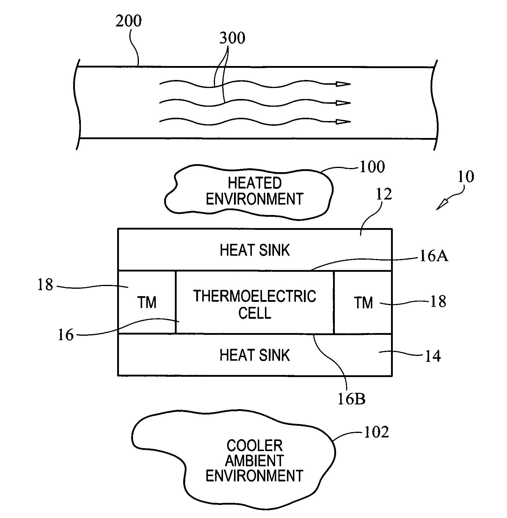
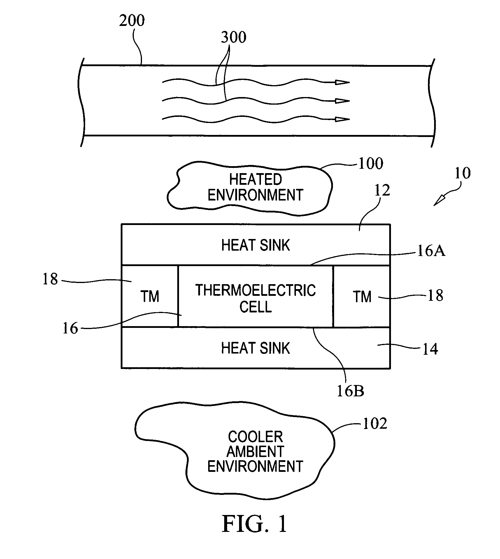
[0016]Referring now to the drawings and more particularly to FIG. 1, an energy conversion assembly that will be used in an energy harvesting system of the present invention is shown and is referenced generally by numeral 10. As will be explained further below, a number of assemblies 10 will be used in an energy harvesting system. By way of example, such an energy harvesting system will be explained for its use with a ship's exhaust stack as a means to convert thermal energy just outside of the exhaust stack to electric energy for storage and use onboard the ship. In this way, embodiments of the present invention can be readily adapted for use with existing exhaust systems. However, it is to be understood that the present invention can be used to convert thermal energy to electric energy where the thermal energy is found within or at the outside of any conduit or tank containing a heated material or fluid.

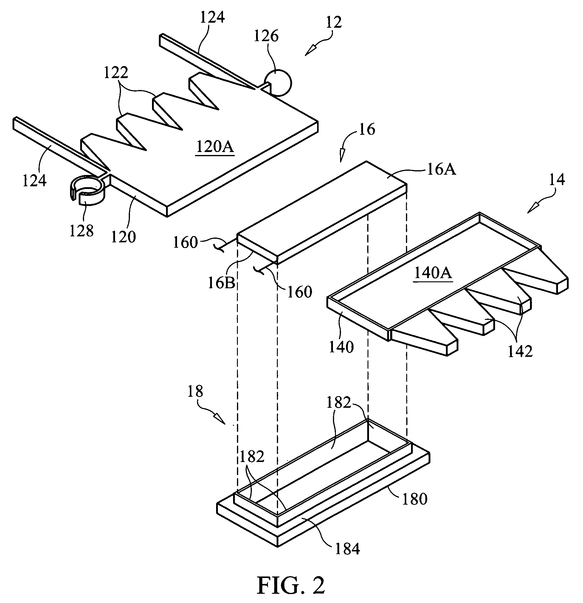
[0017]Energy conversion assembly 10 includes two heat sinks 12 and 14 sandwiche...


PUM


Abstract

A system for harvesting electric energy from thermal energy includes energy conversion assemblies that can be distributed about a conduit through which a heated effluent flows. Each energy conversion assembly includes two heat sinks, a thermoelectric cell sandwiched between the two heat sinks, and a thermal insulating gasket surrounding the thermoelectric cell and separating the two heat sinks. Circuit wiring electrically connects to each thermoelectric cell where the energy conversion assemblies are electrically connected to one another in parallel. An electric power storage device is coupled to the circuit wiring.

Description

[0001]The invention described herein may be manufactured and used by or for the Government of the United States of America for Governmental purposes without payment of any royalties thereon or therefore.ORIGIN OF THE INVENTION[0002]1. Field of the Invention[0003]The invention relates generally to energy conversion systems, and more particularly to an energy harvesting system that converts thermal energy present in a conduit-contained effluent to electric energy.[0004]2. Background of the Invention[0005]Reducing dependency on fossil fuels is an ongoing concern for the entire planet. One alternative form of energy under consideration is thermal energy. Currently, many sources of thermal energy are wasted. For example, it is estimated that approximately 80% of all energy generated in an internal combustion engine (powered with fossil fuel) is lost as heat leaving in the engine's exhaust. In terms of a ship underway or even at idle, a tremendous amount of thermal energy is lost as the s...

Claims


Application Information

Patent Timeline
Patent Type & Authority Patents(United States)
IPC IPC(8): H02J7/35H02J7/00
CPCH02J7/35H02J7/34H01L35/00H01L35/30H10N10/13
Inventor WOODALL, ROBERT C.ADAMS, ROBERT G.
Owner NAVY USA AS RESPRESENTED BY THE SEC OF THE
Why Eureka
Try Eureka