Virtual machine system, networking device and monitoring method of virtual machine system

a virtual machine and networking device technology, applied in the direction of multi-programming arrangements, instruments, program control, etc., can solve the problems of significant time-consuming and laborious, and the failure cannot be detected promptly, so as to increase processing latency, high reliability, and high reliability

Active Publication Date: 2014-09-02
HITACHI LTD
View PDF9 Cites 19 Cited by
  • Summary
  • Abstract
  • Description
  • Claims
  • Application Information

AI Technical Summary

Benefits of technology

[0019]In particular, for PaaS using a WAN like the above-described cloud computing, the provider of a data center should promptly notify the carrier if the WAN has developed a fault, or notify the client company if a business application has developed an error. If a fault has occurred in LAN equipment, a physical server, a VMM, or a virtual machine, the provider of the data center should promptly notify the person in charge of equipment operational administrator for restoration. In this way, to provide higher reliability compared with public cloud, PaaS using a WAN is required to promptly locate the part which has developed a fault and to promptly issue a notice depending on the part which has developed a fault to provide stable services.
[0020]This invention has been achieved in view of the above-described problems and an object of this invention is to provide a highly reliable cloud computing services by promptly detecting an increase in processing latency in any of a WAN configuring the cloud computing, LAN equipment in a data center, a VMM in a server, and a virtual machine on a VMM and by promptly locating of the source of the increase in latency.

Problems solved by technology

Consequently, it disadvantageously takes significant time to locate the part which has developed a fault, so that a fault cannot be detected promptly.

Method used


Image

  • Virtual machine system, networking device and monitoring method of virtual machine system
  • Virtual machine system, networking device and monitoring method of virtual machine system
  • Virtual machine system, networking device and monitoring method of virtual machine system

Examples


first embodiment

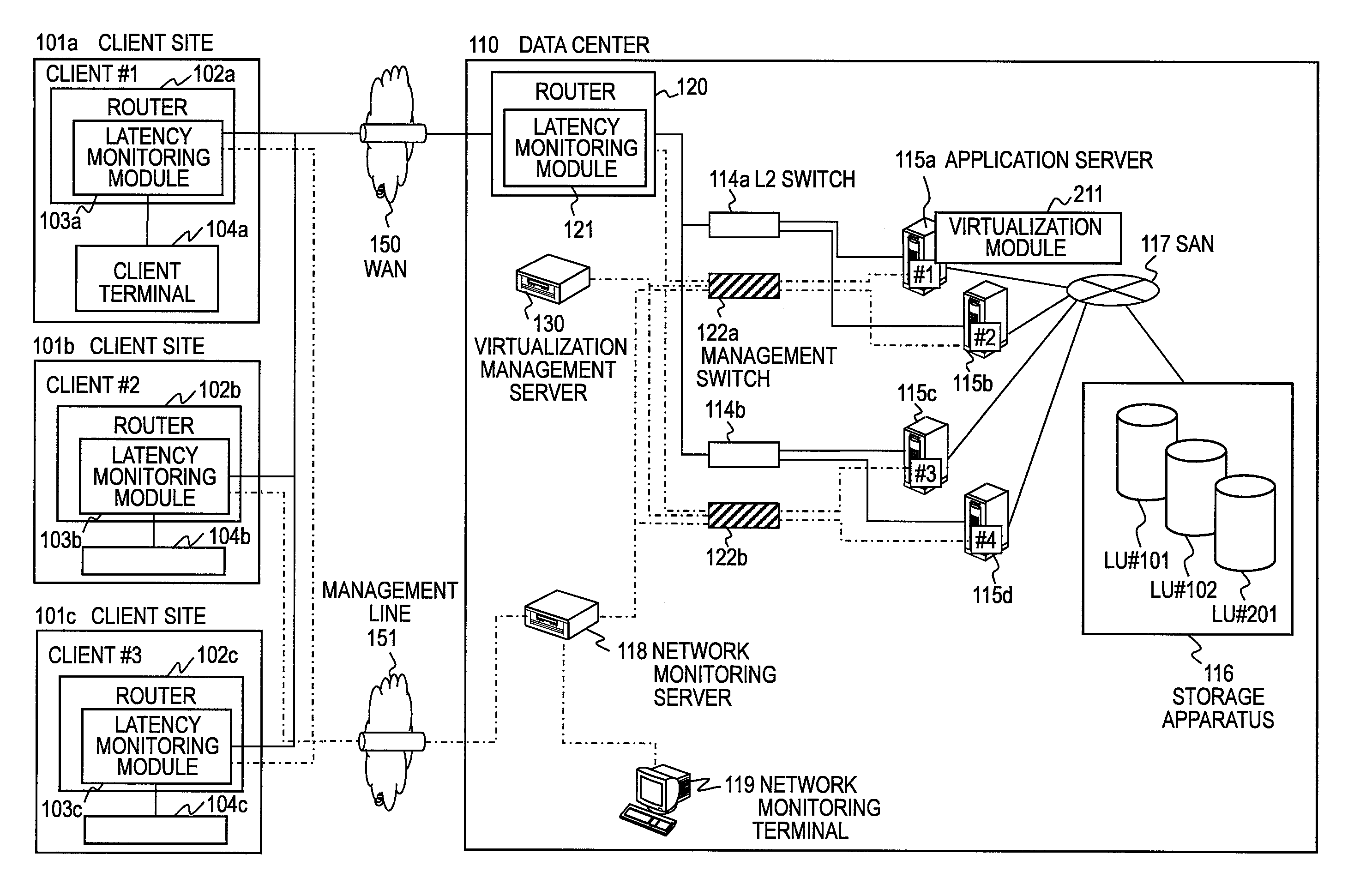
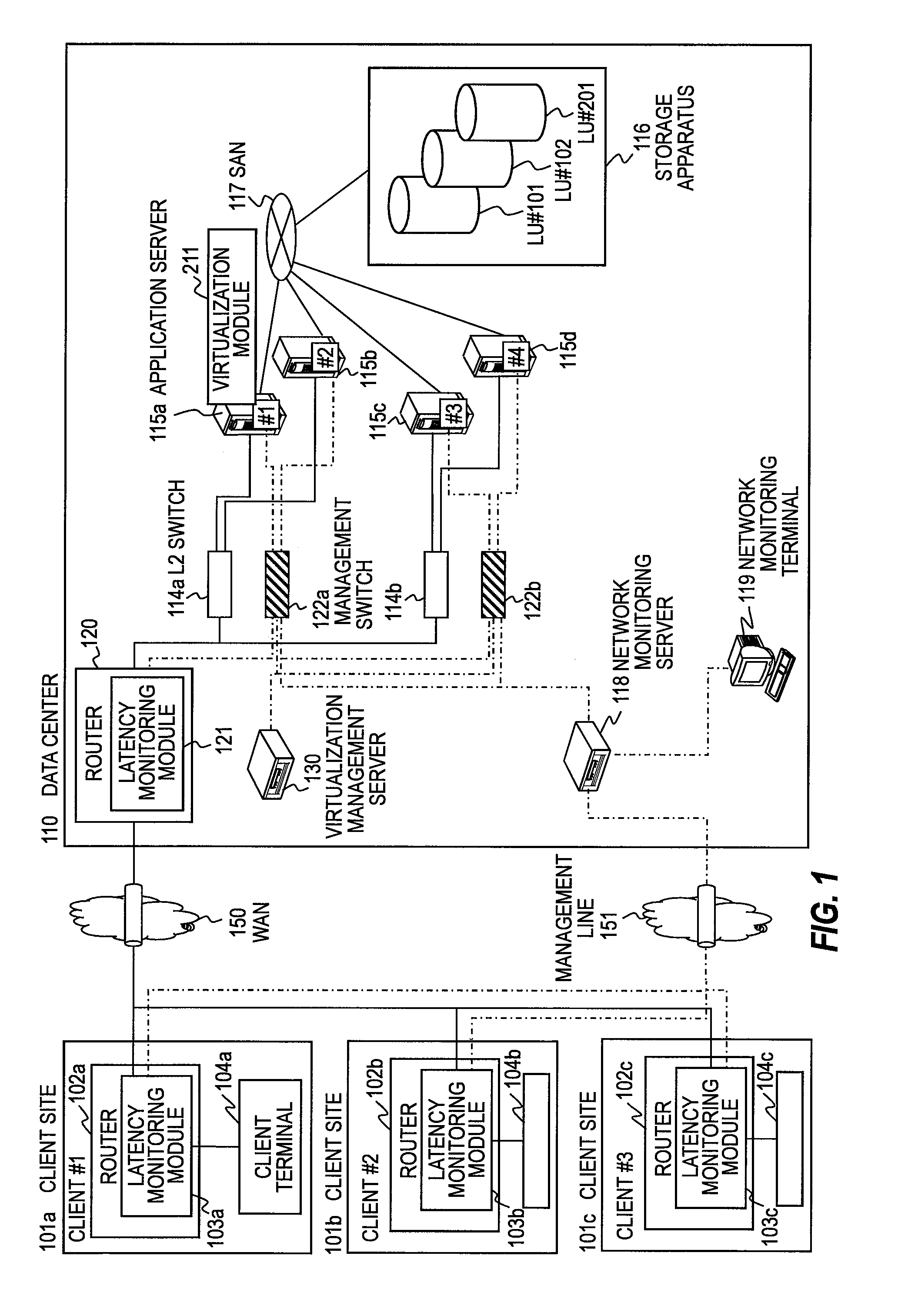
[0037]FIG. 1 is a block diagram exemplifying a computer system that provides cloud services using a WAN (wide area network) to illustrate a first embodiment of this invention.

[0038]A data center 110 for providing cloud services is connected with client sites 101a, 101b, and 101c via a WAN 150. The client site 101a that uses the cloud services of the data center 110 comprises a router 102a, which is connected to the WAN 150 to transmit and receive packets, and a client terminal 104a, which is connected to the router 102a to receive the cloud services of the data center 110. Likewise, the other client sites 101b and 101c comprise respective routers 102b and 102c connected to the WAN 150 and respective client terminals 104b and 104c for receiving the cloud services. Since the client sites 101a to 101c have the same configuration, only the client site 101a will be explained in the following description and the explanations on the other client sites 101b and 101c will be omitted.

[0039]Th...

second embodiment

[0199]FIG. 11 is a block diagram of an application server 115 to illustrate a second embodiment. The application server 115 in the second embodiment includes a virtual CPU agent to be implemented on an OS 261 in a virtual machine 212, which is a replacement of the CPU performance information collector 242 in the virtualization module 211 in the first embodiment and is a modified example where the CPU performance information collector 242 in the first embodiment has been moved from the virtualization module 211 to the OS 261. The other configurations are the same as that of the first embodiment.

[0200]In the second embodiment, on the OSs 261-1 to 261-n in the virtual machines 212-1 to 212-n, business applications 262-1 to 262-n in the first embodiment run, and additionally, virtual CPU monitoring agents 1101-1 to 1101-n are implemented. Since the virtual CPU monitoring agents 1101-1 to 1101-n have the same configuration, only the shown virtual CPU monitoring agent 1101-n will be expla...

third embodiment

[0209]FIG. 12 is a block diagram of a router 1200 to illustrate a third embodiment. The router 1200 in the third embodiment is configured by including the functional components of the network monitoring server 118 shown in FIG. 3 in the first embodiment in the router 120. It can work as a network device equipped with a module for locating the source of performance degradation.

[0210]Hardware resources 1210 of the router 1200 include a CPU 1221, a memory 1223, a storage device 1224, and a communication processor 1222 having a plurality of ports.

[0211]The latency monitoring module 121 and the functional components of the network monitoring server 118 shown in FIG. 3 in the first embodiment are connected within the router 1200. The same components as those in the first embodiment are denoted by the same reference signs and the repetitive explanations thereof are omitted.

[0212]In this third embodiment, like in the first embodiment, the router 1200 monitors the latency in the communicatio...


PUM


Abstract

A method of monitoring a virtual computer system including a network device coupled to a client computer, sever computers each coupled to the network device, and a performance degradation source locator apparatus coupled to the network device and the server computer, obtaining, by the performance degradation source locator apparatus, performance information on physical computer resources and performance information on virtual computer resources of extracted virtual machines and server computers and the virtual machine and the server computer in which the latency has increased to locate a part in which the latency has increased.

Description

CLAIM OF PRIORITY[0001]The present application claims priority from Japanese patent application JP2010-133708 filed on Jun. 11, 2010, the content of which is hereby incorporated by reference into this application.BACKGROUND OF THE INVENTION[0002]This invention relates to a virtual computer system that provides services to be executed by a plurality of virtual machines via a network and a technique to locate a part where performance has degraded in the virtual computer system and in particular, relates to improvement of a virtual computer system that provides cloud computing.[0003]Economic globalization and consequent fiercer competition require continuous innovation in businesses. As to IT systems to support business activities, it is not uncommon that system constructions are requested within such an extremely short period as a month or two for new services to be released, so that companies take on heavy burden of costs to construct and maintain their own (in-house) IT systems. To ...

Claims


Application Information

Patent Timeline
Patent Type & Authority Patents(United States)
IPC IPC(8): G06F9/455G06F9/46G06F9/50
CPCG06F9/5005G06F9/45558G06F11/3409G06F11/3419G06F11/3495G06F2009/45591G06F2201/815H04L41/046H04L43/0817H04L43/0852H04L43/16H04L67/10H04L43/20
Inventor MORIKI, TOSHIOMIYASUDA, YOSHIKO
Owner HITACHI LTD
Why Eureka
Try Eureka