Locking device for pole

a technology of locking device and pole, which is applied in the direction of rod connection, hose connection, sport apparatus, etc., can solve the problems of not exerting sufficient locking force, limiting the length of the cam lever, and substantially large locking force, etc., to achieve small operating force, increase the locking force, and good durability

Active Publication Date: 2014-09-16
LAH JEH KUN
View PDF28 Cites 25 Cited by
  • Summary
  • Abstract
  • Description
  • Claims
  • Application Information

AI Technical Summary

Benefits of technology

[0013]Accordingly, the present invention has been made in view of the above-mentioned problems occurring in the prior art, and it is an object of the present invention to provide a locking device for a pole which is capable of requiring a relatively small operating force, greatly increasing a locking force, and maintaining good durability in spite of repeated uses.

Problems solved by technology

As a result, there is a limit in extending the whole length of the cam lever 40, which fails to exert a sufficient locking force, and further, a substantially large locking force should be needed when the locking is carried out, which really makes it for old people or women to do that.

Method used


Image

  • Locking device for pole
  • Locking device for pole
  • Locking device for pole

Examples


first embodiment

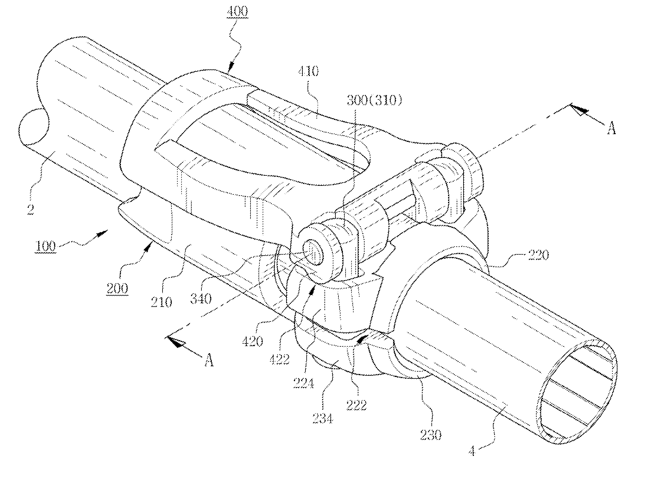
[0037]As shown in FIGS. 4 to 6, a locking device 100 for a pole according to the present invention is mounted on the end peripheral surface of an upper connection tube 2 having a large diameter, and an axial lever 400 is rotated to fix a lower connection tube 4 having a smaller diameter than the upper connection tube 2 or to release the fixed state.

[0038]According to the first embodiment of the present invention, the locking device 100 includes: a grasping tube 200 having incision portions 222 formed at the left and right sides in the radial direction thereof in such a manner as to provide an upper arch-shaped grasping piece 220 and a lower arch-shaped grasping piece 230 formed independently on the upper and lower portions thereof; operating pins 300 adapted to be passed in an up and down direction through both sides of the upper arch-shaped grasping piece 220 and the lower arch-shaped grasping piece 230; and the axial lever 400 adapted to be fastened to the operating pins 300 in su...

second embodiment

[0057]FIGS. 12 to 14 show a locking device for a pole according to the present invention, wherein FIG. 12 is a perspective view thereof, FIG. 13 is a perspective view showing a loosening prevention pad of FIG. 12, and FIG. 14 is a sectional view showing the assembling state wherein the loosening prevention pad is adopted.

[0058]According to the second embodiment of the present invention, the configuration is the same as the first embodiment of the present invention, except that operating pins 300 are configured differently from those in the first embodiment of the present invention, loosening prevention pads 500 are additionally provided to fix the operating pins 300 thereto, and the coupling structure between the hinge pin 340 and a fixing pin 350a is different from that in the first embodiment of the present invention.

[0059]The loosening prevention pads 500 restrict the adjusting screws 320 coupled to the upper pins 310 so as to prevent the whole lengths of the operating pins 300 f...


PUM


Abstract

The present invention relates to a locking device for a pole, including: a grasping tube having incision portions; operating pins adapted to be inserted in an up and down direction into upper and lower pressing parts; and an axial lever having a pressing plate extended in the lengthwise direction of the pole.

Description

BACKGROUND OF THE INVENTION[0001]1. Field of the Invention[0002]The present invention relates to a locking device for a pole that performs a locking operation through an axial lever, and more particularly, to a locking device for a pole wherein an axial lever is disposed in the lengthwise direction of the pole to apply a clamping force to both left and right sides of upper and lower connection tubes in the radial direction, thereby requiring a relatively small operating force, increasing a locking force, and allowing fine adjustment in the locking force to be carried out.[0003]2. Background of the Related Art[0004]Generally, poles such as hiking poles, sports game poles, patient's walking assistant poles, and the like are used as auxiliary means for supporting a user's body. The pole is provided with a pole body and a handle connected to the end of the pole body. The pole body is generally formed by insertedly coupling a plurality of connection tubes in such a manner as to be foldab...

Claims


Application Information

Patent Timeline
Patent Type & Authority Patents(United States)
IPC IPC(8): F16B2/10A63C11/22F16B7/14
CPCA63C11/221F16B7/1418Y10T24/1412Y10T24/44017Y10T24/1451Y10T24/1424
Inventor LAH, JEH-KUN
Owner LAH JEH KUN
Why Eureka
Try Eureka