Rail vehicle with variable axial geometry

a technology of axial geometry and rail vehicles, applied in passenger carriages, railway components, underframes, etc., can solve problems such as fatigue, negative effects of rails and wheels, and profile wear by removing materials, and achieve the effect of reducing the cost of actuators required

Inactive Publication Date: 2014-09-16
SIEMENS MOBILITY AUSTRIA GMBH
View PDF29 Cites 3 Cited by
  • Summary
  • Abstract
  • Description
  • Claims
  • Application Information

AI Technical Summary

Benefits of technology

[0012]An object is to specify a rail vehicle with variable axle geometry which can adjust any given positions (angular position and lateral displacement) of the axles determined by means of a model-based method while the rail vehicle is moving and minimize the expense of actuators required for this.
[0015]The inventive rail vehicle or the inventive bogie respectively are especially advantageously suitable for implementation in the method described in the unpublished application A942 / 2007 for optimizing the wear behavior, since the constructional outlay is very greatly simplified by the present invention. Of particular significance is the omission of a constructionally extremely complex so-called “lateral actuator”. Likewise the present invention makes it possible to use constructionally simple actuators (for example hydraulic or pneumatic cylinders or electrical actuators). The method described in A942 / 2007 delivers as initial variables the angular position dα between two axles and what is referred to as the lateral displacement. These two variables can, with a rail vehicle in accordance with the present invention, be adjusted exclusively by adjusting the specific horizontal angle of the axles in relation to the vehicle frame, by which a quieter running of the rail vehicle and an optimized wear behavior of the wheels is achieved.
[0016]The advantage achieved by the present invention is that respective optimum values of the angular position dα and the lateral displacement can be adjusted, wherein the horizontal angle of each axle in relation to the vehicle frame is to be provided exclusively as the variable. In particular the present invention makes it possible to dispense with the lateral actuators which are very expensive in terms of their construction.
[0017]The inventive so-called asymmetric activation makes it possible by means of the asymmetric distribution of the angle dα between two axles to perform the explicit adjustment of the lateral displacement at two different angles α1 and α2 without having to provide an actuator for the lateral displacement.
[0018]A preferred embodiment of the invention is to provide a fixed point (vertical pivot point) at one end of the axle and assign an actuator which engages at the other end of the axle. This actuator is inventively attached supported on one side to a fixed point of the vehicle frame and on a second side to the horizontal angularly-displacable support of the assigned axis of the rail vehicle. By means of modulation of the length of the actuator this successfully enables any given horizontal angular positions of each axle to be achieved.
[0019]A further preferred embodiment of the invention makes provision, on successive axles, for the actuators assigned to them to engage alternately on opposing ends of the axles, so that for example an axle of which the actuator is arranged on one side of the rail vehicle is followed by an axle on which the actuator is arranged on the opposite side of the rail vehicle. This makes it possible to achieve the advantage of optimum utilization of the space available in the chassis of the rail vehicle.

Problems solved by technology

These forces are however also responsible for negative effects on the rails and wheels.
Thus tangential forces, which are always associated with sliding effects and thus with friction, cause profile wear by removing material.
Furthermore the forces attacking wheel and rail, with a sufficiently high level of force, cause fatigue in the material, resulting in Rolling Contact Fatigue (RCF).
This results in fine cracks in the rail and / or in the wheel for example.
Head checks represent a typical form of damage caused by this fatigue on the rail surface.
Cracks can occur in the wheel below the surface, grow outwards and lead to larger pits.
However the cracks can also occur on the surface per se, grow deeper and likewise lead to material failures, as also occurs for example in the known phenomenon of the herringbone pattern.
As well as the running surface damage mentioned, a variety of further forms of damage, such as flat spots, material removal, cracks across running surfaces etc., also occur.
Irregularities in the wheel-rail contact, caused for example by serious damage to a wheel, can lead to major consequential damage through to derailment.
But light damage such as fine cracks can also lead to great difficulties, since they make maintenance work necessary and can thus result in high costs and delays in rail traffic.
However rolling contact fatigue also causes damage to rail and wheel.
The so-called lateral actuators required for this render the construction of the bogie extraordinarily difficult.

Method used


Image

  • Rail vehicle with variable axial geometry
  • Rail vehicle with variable axial geometry
  • Rail vehicle with variable axial geometry

Examples


Embodiment Construction

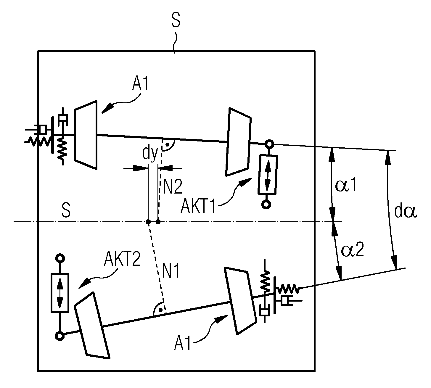
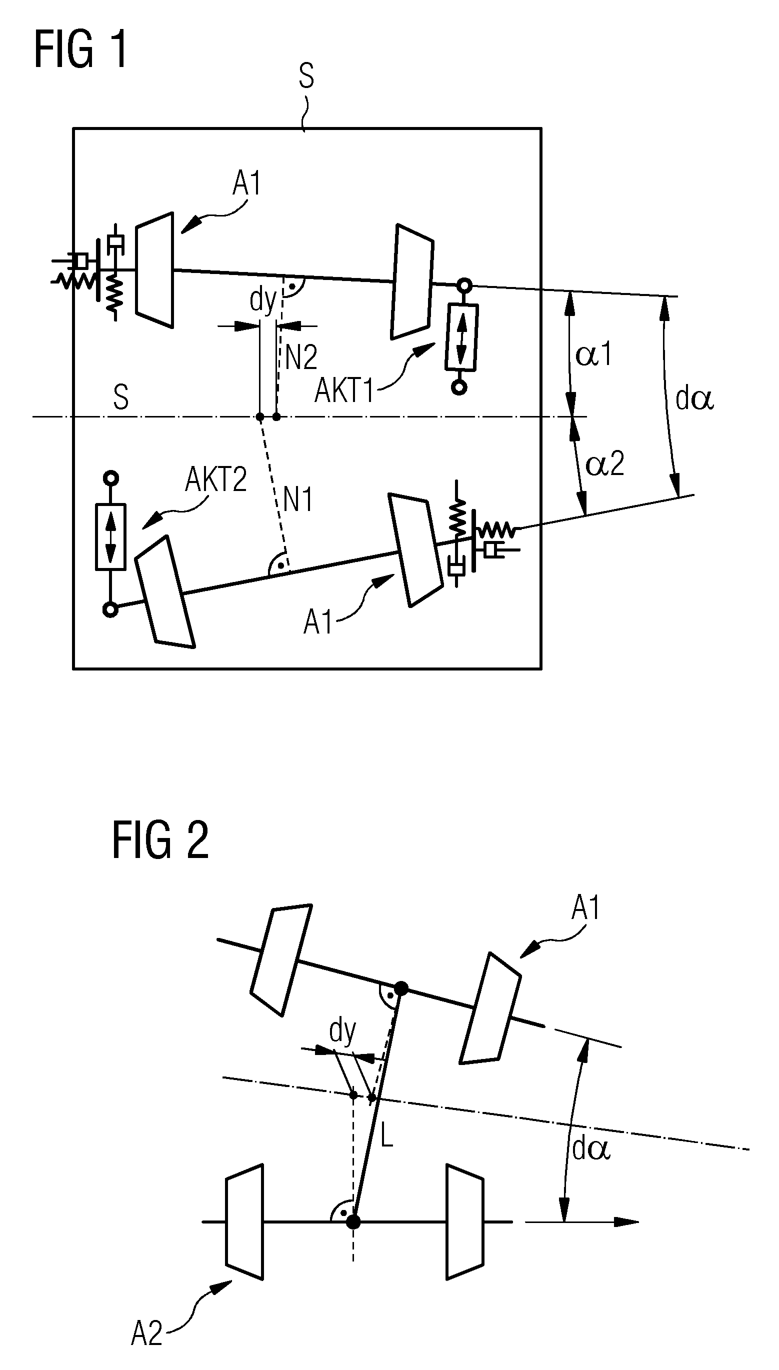
[0029]As an example and a schematic, FIG. 1 shows the principle structure of a rail vehicle with variable axle geometry. A rail vehicle S comprising two axles A1, A1, which are each supported horizontally around a pivot point at one end of each variable axle A1, A2. On the side of each axle A1, A2 opposite the pivot point an actuator AKT1, AKT2 engages respectively at the end of each axle A1, A2, which is connected at its other end to the frame of the rail vehicle S. By means of modulation of the length of the actuators AKT1, AKT2 a separate specific horizontal angle α1, α2 can thus be set for each axle A1, A2. If different horizontal angles α1, α2 are set for consecutive axles a lateral displacement dy and an axle angle dα of α1+α2 is produced between these axles. It is shown that as well as the axle angle dα, the lateral displacement dy has a decisive influence on the wear or damage behavior of the vehicle.

[0030]This lateral displacement dy is defined geometrically by the normals ...


PUM


Abstract

A rail vehicle with variable axial geometry includes at least two axles, wherein a horizontal angular position of each axle with respect to the vehicle frame may be changed, and wherein the angular position of each axle is adjusted continuously during operation of the rail vehicle in such a way that a predefined lateral displacement and a predefined axial angle are achieved.

Description

CROSS REFERENCE TO RELATED APPLICATIONS[0001]This application is the US National Stage of International Application No. PCT / EP2011 / 054719 filed Mar. 28, 2011, and claims the benefit thereof. The International Application claims the benefits of European Patent Application No. 10158173.4 EP filed Mar. 29, 2010. All of the applications are incorporated by reference herein in their entirety.FIELD OF INVENTION[0002]The invention relates to a rail vehicle with variable axial geometry.BACKGROUND OF INVENTION[0003]The forces necessary to guide a vehicle along a railway track occur in the area of contact between wheel and rail, the wheel-rail contact. These forces are however also responsible for negative effects on the rails and wheels. Thus tangential forces, which are always associated with sliding effects and thus with friction, cause profile wear by removing material. Furthermore the forces attacking wheel and rail, with a sufficiently high level of force, cause fatigue in the material,...

Claims


Application Information

Patent Timeline
Patent Type & Authority Patents(United States)
IPC IPC(8): B61D1/00B61F5/38
CPCB61F5/38
Inventor SIX, KLAUSTEICHMANN, MARTIN
Owner SIEMENS MOBILITY AUSTRIA GMBH
Why Eureka
Try Eureka