Magnification compensating sighting systems and methods

a sighting system and compensating technology, applied in the field of magnification compensating sighting systems and methods, can solve the problems of inaccurate shots, inconvenient adjustment of sight, rushed or novice riflemen forgetting to adjust the sight to maximum magnification,

Active Publication Date: 2014-09-16
BURRIS
View PDF99 Cites 39 Cited by
  • Summary
  • Abstract
  • Description
  • Claims
  • Application Information

AI Technical Summary

Problems solved by technology

Some of those steps may be forgotten by an inexperienced or rushed rifleman, leading to inaccurate shots.
Sometimes, however, rushed or novice riflemen forget to adjust the sight to maximum magnification.
Since the optical device displays or identifies the ideal aiming point based on a specific (usually a maximum) magnification set point, an inaccurate shot may be taken if the rifleman fails to set the magnification to the correct setting.

Method used


Image

  • Magnification compensating sighting systems and methods
  • Magnification compensating sighting systems and methods
  • Magnification compensating sighting systems and methods

Examples


Embodiment Construction

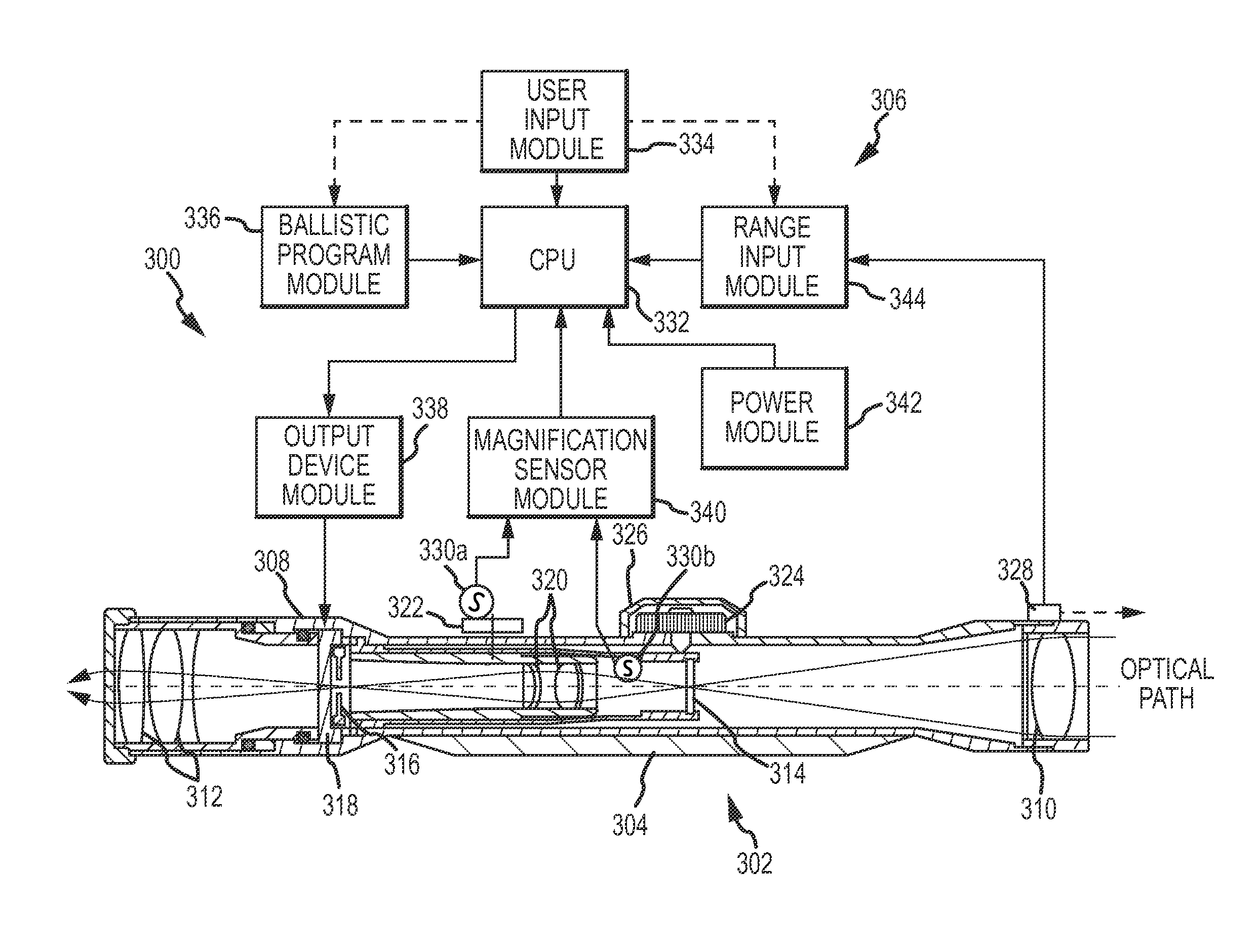
[0018]The present technology relates to new and improved embodiments of known sighting systems and methods (such as those described in U.S. Pat. No. 7,703,679, the disclosure of which is hereby incorporated by reference herein in its entirety), for correctly aiming a firearm or other implement. As used herein, a “sighting system” shall be construed broadly and is defined as one or more optical devices and processing systems that assist a person in aiming a projectile launch system, such as a firearm, a rifle, or other implement. The disclosed technology has application in any type of sighting system or optical device, including those with addressable aiming elements and those without. In this application, a riflescope will be described as an exemplary embodiment.

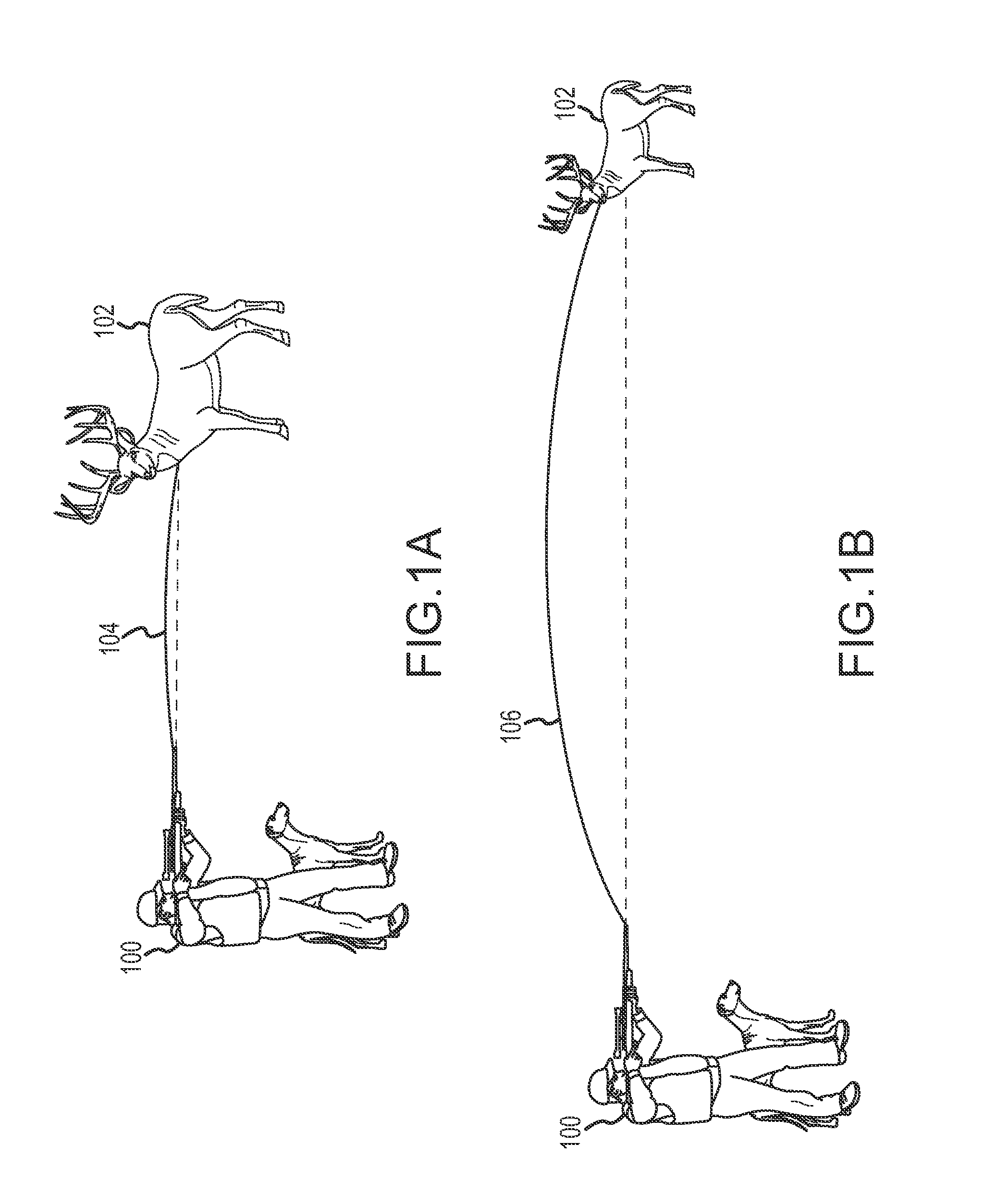
[0019]A hunter, sniper, or other person using a rifle or other firearm, commonly referred to as a shooter, uses optical sighting systems, such as riflescopes, to visually acquire a target and improve aiming accuracy. General...


PUM


Abstract

A method is used to determine an aiming point for a sighting system used by a shooter to shoot a target. The method includes receiving a range signal that corresponds to a distance from the shooter to the target. A first position signal is received from a magnification system sensor. A first magnification setting based at least in part on the first position signal is then determined. Thereafter, a first aiming point based at least in part on both of the range signal and the first magnification setting is determined.

Description

CROSS-REFERENCE TO RELATED APPLICATION[0001]The present application claims priority to and the benefit of U.S. Provisional Application Ser. No. 61 / 490,524, filed May 26, 2011, entitled “Magnification Compensating Sighting Device and Methods,” the disclosure of which is hereby incorporated by reference herein in its entirety.INTRODUCTION[0002]Aiming a rifle or gun requires the consideration of several environmental and other types of factors. When a bullet travels from a rifle to an intended target, several forces affect the flight of the bullet. Gravity causes the bullet to drop in elevation as the bullet travels from the firearm to the target. If a hunter 100 is close to his / her target 102, as shown in FIG. 1A, the bullet drops very little, represented by the adjusted trajectory 104. However, improvements in firearms and ammunition have allowed hunters to target game from long distances. At these greater distances, gravity causes a bullet to drop in elevation more significantly, as...

Claims


Application Information

Patent Timeline
Patent Type & Authority Patents(United States)
IPC IPC(8): G06F19/00F41G1/38G06G7/80
CPCF41G1/473F41G1/38F41G3/06G01B11/14F41G3/08F41G1/00
Inventor MCCARTY, JOHNSTODDARD, WALTER D.PATERSON, DOUGLAS F.
Owner BURRIS
Why Eureka
Try Eureka