
Receive beamformer for ultrasound

a beamformer and ultrasound technology, applied in tomography, applications, instruments, etc., can solve the problems of significantly limiting the number of data channels and thus the spatial resolution provided, power dissipation, cooling requirements, etc., to save gate count, reduce power consumption, and reduce computational intensity.

Active Publication Date: 2014-09-16
TEXAS INSTR INC
View PDF49 Cites 6 Cited by
  • Summary
  • Abstract
  • Description
  • Claims
  • Application Information

AI Technical Summary

Benefits of technology

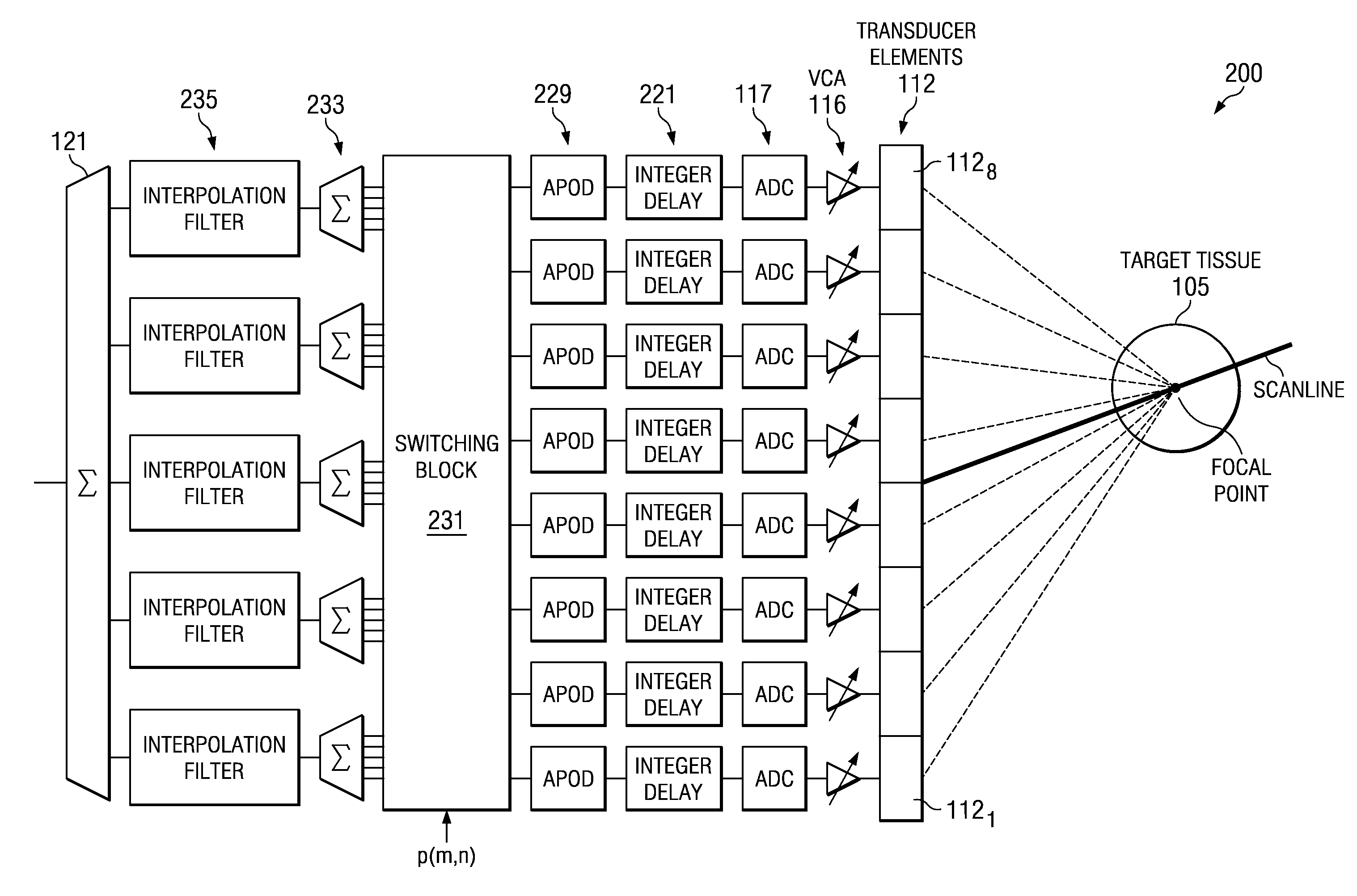
[0022]Embodiments of the invention describe new data path architectures for ultrasound receive beamforming applications involving a plurality transducer elements that are less computationally intensive as compared to conventional data architectures for ultrasound receive beamforming. Embodiments of the invention enable a significant reduction in the number of multiplies as compared to the conventional data path architecture described above, and generally provide mathematically equivalent signals so that the same quality images can generally be generated therefrom. The reduction in number of multiplies can be used to save gate count and lower power in a given implementation, or enable the use of more data channels to improve system performance.
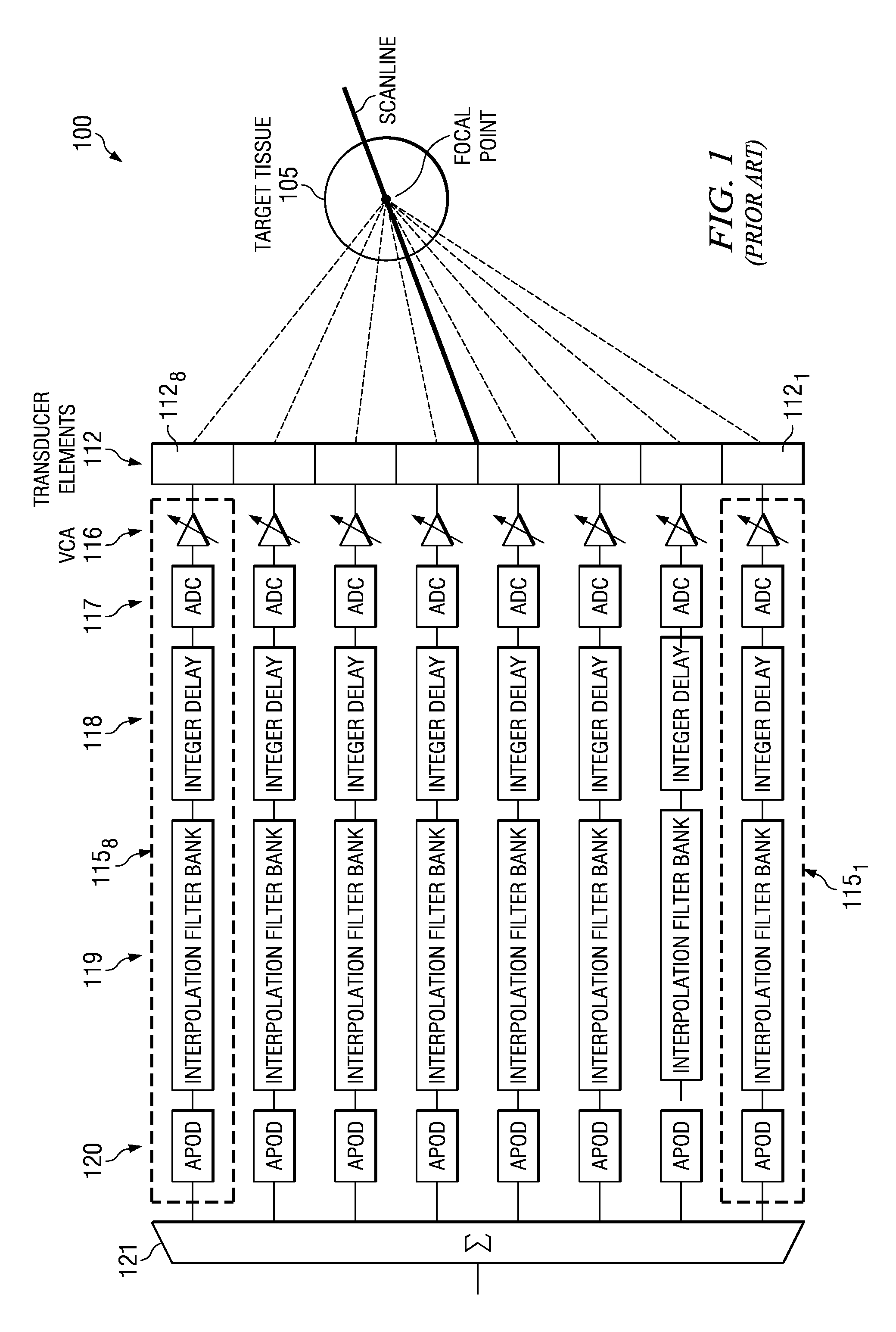
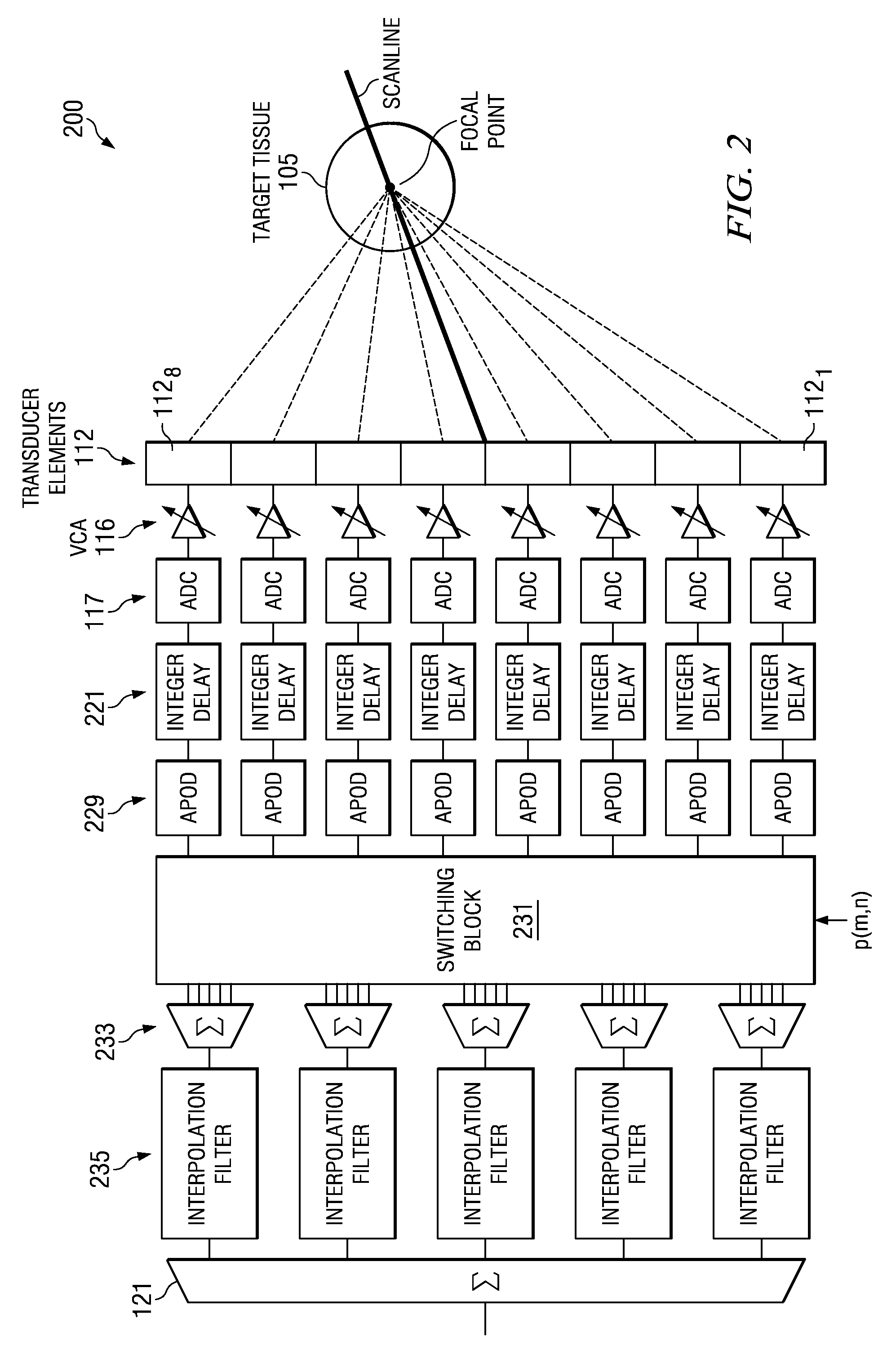
[0023]The Inventor has recognized that the dedicated interpolation filter bank requirement for each data channel associated with each of the M transducer elements, such as a dedicated interpolation filter bank 119 (having P interpolation filters) for each of the transducer elements 1121-1128 shown in FIG. 1 for conventional delay and sum ultrasound receive beamformer system 100, can be eliminated. By implementing a suitable switching network as described below that allows combining data originating from a plurality of different transducer elements to any of a plurality of interpolation filters in a shared interpolation filter bank, the dedicated interpolation filter bank requirement for conventional beamformer systems can be removed.
[0024]Embodiments of the invention thus generally implement data path combining before interpolation filtering, rather than the data path combining after interpolation filtering in conventional architectures. As a result, the minimum number of interpolation filter banks is one, which allows a significantly lower gate count, and as a result lower power and thus a lower cooling requirement for a given circuit implementation.

Problems solved by technology

The numMults required in a beamformer algorithm determines the gate count in an IC implementation, and as a result the power dissipation and thus the cooling requirements for a given implementation.
Due to the high numMults required for implementing the algorithm used by conventional beamformer data architecture, such as implemented by the delay and sum ultrasound receive beamformer system 100 shown in FIG. 1, such conventional beamformers have generally been limited to ASIC implementations and have had to significantly limit the number of data channels and thus the spatial resolution provided.
For high channel count systems (e.g., 128 transducers / data channels) even with the gate count efficiencies provided by data path architectures according to embodiments of the invention, receive beamforming implementation on a single DSP chip may not be feasible absent some complex or elaborate cooling arrangement, due to power budget considerations.

Method used


Image

  • Receive beamformer for ultrasound
  • Receive beamformer for ultrasound
  • Receive beamformer for ultrasound

Examples


examples

[0059]Embodiments of the invention are further illustrated by the following specific examples, which should not be construed as limiting the scope or content of embodiments of the invention in any way.

[0060]FIG. 7 shows a comparison of the number of multipliers numMults required for a conventional (shown as the “baseline implementation”) ultrasound receive data architecture implementation and an ultrasound receive data architecture implementation according to an embodiment of the invention (shown as the “new implementation”) for a selected variety of parameters, including sampling rate (MHz), delay accuracy, number of transducer elements / channels, filter order and MLAs. As the number of MLAs increases, the relative performance / efficiency of algorithms according to an embodiment of the invention improves. For a given number of transducer elements (M), the performance of algorithms according to an embodiment of the invention decreases as the number of interpolation filters (P) increas...


PUM


Abstract

A method of ultrasound receive beamforming includes receiving a first plurality of sensing signals from target tissue, forming a first plurality of digital sensing signals, and data processing the digital sensing signals along a first plurality of data paths to form a first plurality of delayed and apodized digital sensing signals. Data path combining generates data combinations of the delayed and apodized digital sensing signals to include two or more of the delayed and apodized digital sensing signals that originate from different ones of the transducer elements. The data combinations are interpolation filtered using a plurality of interpolation filters to form a second plurality of delayed and apodized digital sensing signals, which are then summed to form an ultrasound receive beamformed signal. The interpolation filters can be interpolation filters in a single shared filter bank, with each interpolation filter providing a different fractional delay.

Description

CROSS REFERENCE TO RELATED APPLICATIONS[0001]This application claims the benefit of Provisional Application Ser. No. 61 / 076,173 entitled “A REDUCED COMPLEXITY BEAMFORMER FOR ULTRASOUND APPLICATIONS” filed Jun. 27, 2008, which is herein incorporated by reference in its entirety.FIELD OF THE INVENTION[0002]Embodiments of the invention relate to receive beamformers for ultrasound and related beamforming algorithms, and integrated circuits (ICs) and ultrasound systems therefrom.BACKGROUND[0003]Beamforming is a signal processing technique used in sensor arrays for directional signal transmission or reception. Spatial selectivity is achieved by using adaptive or fixed receive / transmit beam patterns.[0004]Beamforming can be used for both electromagnetic waves (e.g., RF) and sound waves, and has found a variety of applications in radar, seismology, sonar, wireless communications, radio astronomy, speech, and medicine. Adaptive beamforming is used to detect and estimate the signal-of-interes...

Claims


Application Information

Patent Timeline
Patent Type & Authority Patents(United States)
IPC IPC(8): A61B8/00G01S7/52G01S15/89G10K11/34
CPCG10K11/346G01S7/52046G01S15/8915
Inventor MAGEE, DAVID, P
Owner TEXAS INSTR INC
Learn More