Eureka AIR delivers breakthrough ideas for toughest innovation challenges, trusted by R&D personnel around the world.

System and method for simulating machining objects

a technology of object and simulation method, applied in the field of simulation machining, can solve the problems of small discrepancies between the actual the desired final shape of the object, and the inability of the g-code generated by the computer aided manufacturing system to produce an exact replication of the desired final shape,

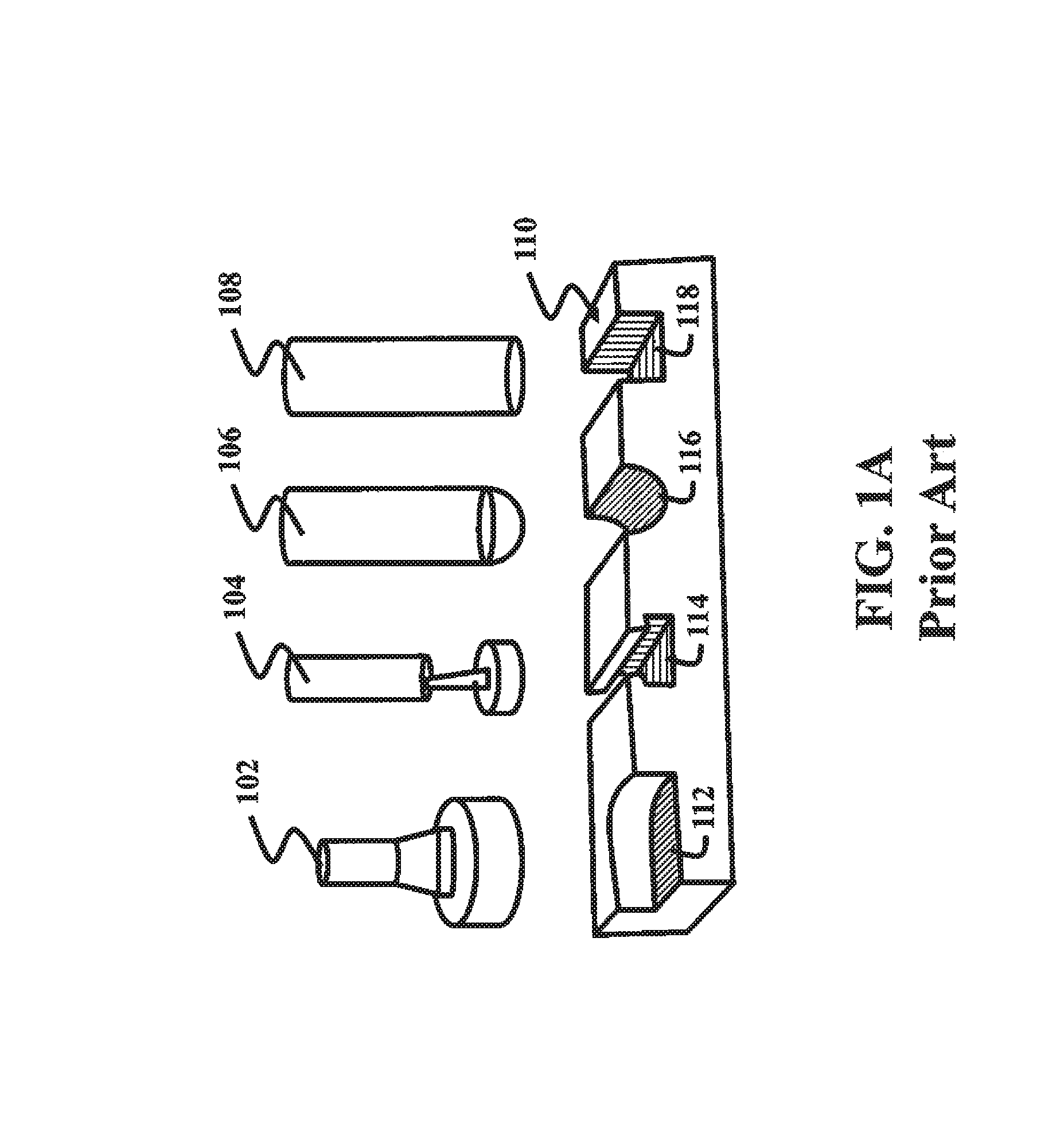
Active Publication Date: 2014-09-16
MITSUBISHI ELECTRIC RES LAB INC
View PDF6 Cites 14 Cited by
  • Summary
  • Abstract
  • Description
  • Claims
  • Application Information

AI Technical Summary

Problems solved by technology

The G-Codes generated by the computer aided manufacturing system can fail to produce an exact replication of the desired final shape.
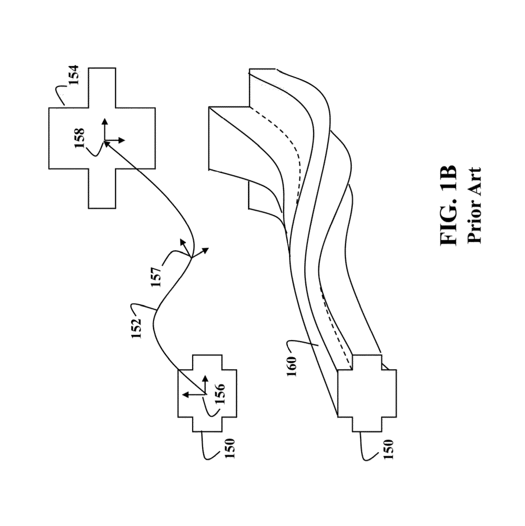
In addition, the motion of the tool and / or object is governed by motors of the NC machining system, which have limited speeds, ranges of motion, and abilities to accelerate and decelerate, so that the actual motions sometimes do not exactly follow the NC machining instructions.
Discrepancies between the actual final shape of the object and the desired final shape of the object can be small, and difficult to observe.
In some situations, these discrepancies result in undesirable gouges or nicks in the surface of the final shape of the object with sizes on the order of a few micrometers in depth and width, and tens of micrometers in length.
However, this manual testing is time consuming and expensive.
Due to the relatively course texture of the sand a sand casting has a rough finish, and low dimensional accuracy.
However, a surface representation of the cast workpiece can be incompatible with representations of the motions of the tool.
However, the conversion process is time consuming and may have large memory requirements.
Also, in the case of free-form surfaces, the conversion may result in a loss of accuracy.

Method used


Image

  • System and method for simulating machining objects
  • System and method for simulating machining objects
  • System and method for simulating machining objects

Examples


example of implementation

[0121

[0122]FIGS. 11-12 show flow charts of a specific, but not intended to be limited example of rendering process into an image according to one embodiment of the invention. The image is displayed on a screen of a display device having screen coordinate system. The rendering proceeds in two phases. In the first phase the BP object is rendered such that any BP fragments of the BP object having world space position external to the MP object are not added to a frame buffer of the image. In the second phase the rendering of the MP object is performed only for those pixels corresponding to BP object fragments external to the MP object, i.e., from the set of machined BP fragments.

[0123]FIG. 11 shows a flow chart of the first phase of the rendering. During the first phase, the method iterates 1101 over all of faces of the BP object. Each face is projected 1102 from world coordinate system to the screen coordinate system and then rasterized 1103 to determine a fragment corresponding to a l...


PUM


Abstract

A computer simulation of machining of an object by a motion of a tool is described. The object is represented by a boundary representation (BP) object, wherein the BP object includes a boundary representation of a surface of the object, wherein the motion is represented by a set of swept volumes, wherein the set of swept volumes includes a first set of implicit functions defining a surface of the set of swept volumes. The simulation includes determining a proxy object having a second set of implicit functions defining a surface of the proxy object; simulating the machining of the proxy object with the set of swept volumes to produce a machined proxy (MP) object having a third set of implicit functions defining a surface of the MP object; rendering an image of a Boolean intersection between the MP object and the BP object.

Description

FIELD OF INVENTION[0001]The invention relates generally to simulating machining, and more particularly to a system and a method for simulating machining the objects using a Boolean intersection.BACKGROUND OF THE INVENTION[0002]Numerically Controlled Machining[0003]Simulating numerically controlled (NC) machining, e.g., turning, boring, drilling, broaching, sawing, shaping, reaming, milling, tapping, grinding, is important in computer aided design (CAD) and computer aided manufacturing (CAM). During the simulation, a model of an object, e.g., a workpiece, is edited with a computer representation of a tool, e.g., an NC milling tool, and a set of motions, which simulate the machining process.[0004]The simulation visualizes the model of the object and the representation of the tool on a display device to detect potential collisions between parts, such as the workpiece and the tool holder, and to verify a final shape of the object.[0005]The final shape of the object is affected by the se...

Claims


Application Information

Patent Timeline
Patent Type & Authority Patents(United States)
IPC IPC(8): G06F17/50G06F19/00G06T15/00G06F17/10G06F7/60G06T17/00G05B19/4069G05B19/4097
CPCG05B19/4069G05B19/4097Y02P90/02
Inventor SULLIVAN, ALANMANUKYAN, LIANA
Owner MITSUBISHI ELECTRIC RES LAB INC
Why Eureka
Eureka Blog
Learn More