
Failover mechanism

a failure mechanism and failure technology, applied in the field of failure mechanisms, can solve the problems of increasing increasing and complicating virtualization networking, so as to reduce configuration and maintenance overhead, simplify networking, and increase the overall system throughput

Active Publication Date: 2014-09-16
MICROSOFT TECH LICENSING LLC
View PDF14 Cites 2 Cited by
  • Summary
  • Abstract
  • Description
  • Claims
  • Application Information

AI Technical Summary

Benefits of technology

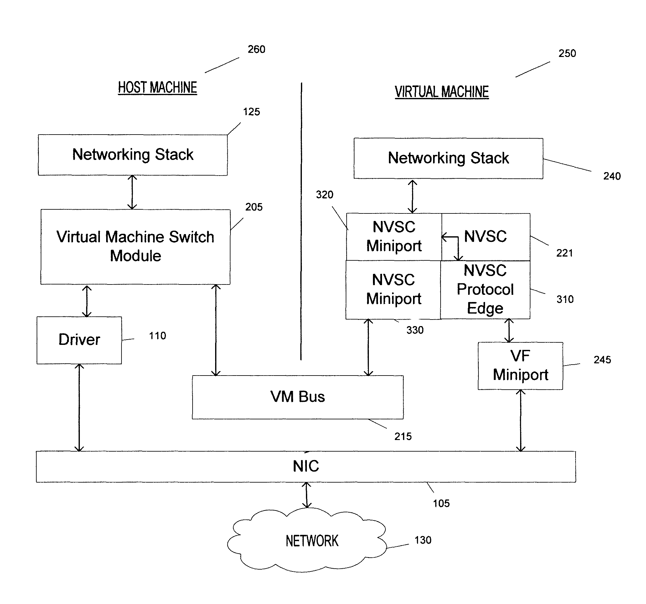
[0004]The inventors have recognized that virtualization can complicate networking. For example, some host computers that receive information over a network may employ multiple paths to transfer the information to virtual machines on the computer, and to transfer the information from a virtual machine to the network. In configurations that provide multiple paths within the host computer for transferring information to and from virtual machines, a failover capability is useful (e.g., in case one of the multiple paths becomes unavailable, or it is less desirable to use one path than another). Failover capability may, for example, be provided by an intermediate driver component introduced into the configuration. The inventors have recognized, however, that a solution which does not introduce an intermediate driver component may provide even greater overall system throughput, and decrease configuration and maintenance overhead. As a result, some embodiments of the invention provide a failover capability in a computer system that employs multiple paths to transfer information to and from virtual machines, without introducing an intermediate driver component to do so.

Problems solved by technology

The inventors have recognized that virtualization can complicate networking.
The inventors have recognized, however, that a solution which does not introduce an intermediate driver component may provide even greater overall system throughput, and decrease configuration and maintenance overhead.

Method used


Image

  • Failover mechanism
  • Failover mechanism
  • Failover mechanism

Examples


Embodiment Construction

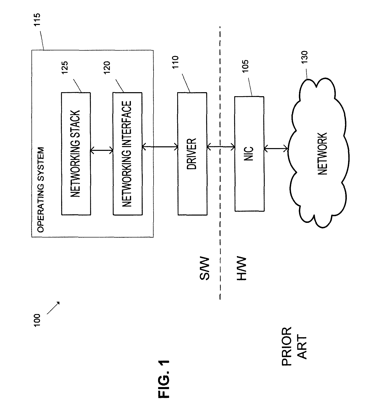
[0011]As noted above, the inventors have recognized that virtualization can complicate networking. For example, some host computers that receive information over a network may employ multiple paths to pass the information from a physical network interface to virtual machines on the computer, and to pass information from a virtual machine for delivery over the network. Providing a failover capability, so that if any of the paths becomes unavailable another path can be used to pass information, can complicate the processing of information received via a network.

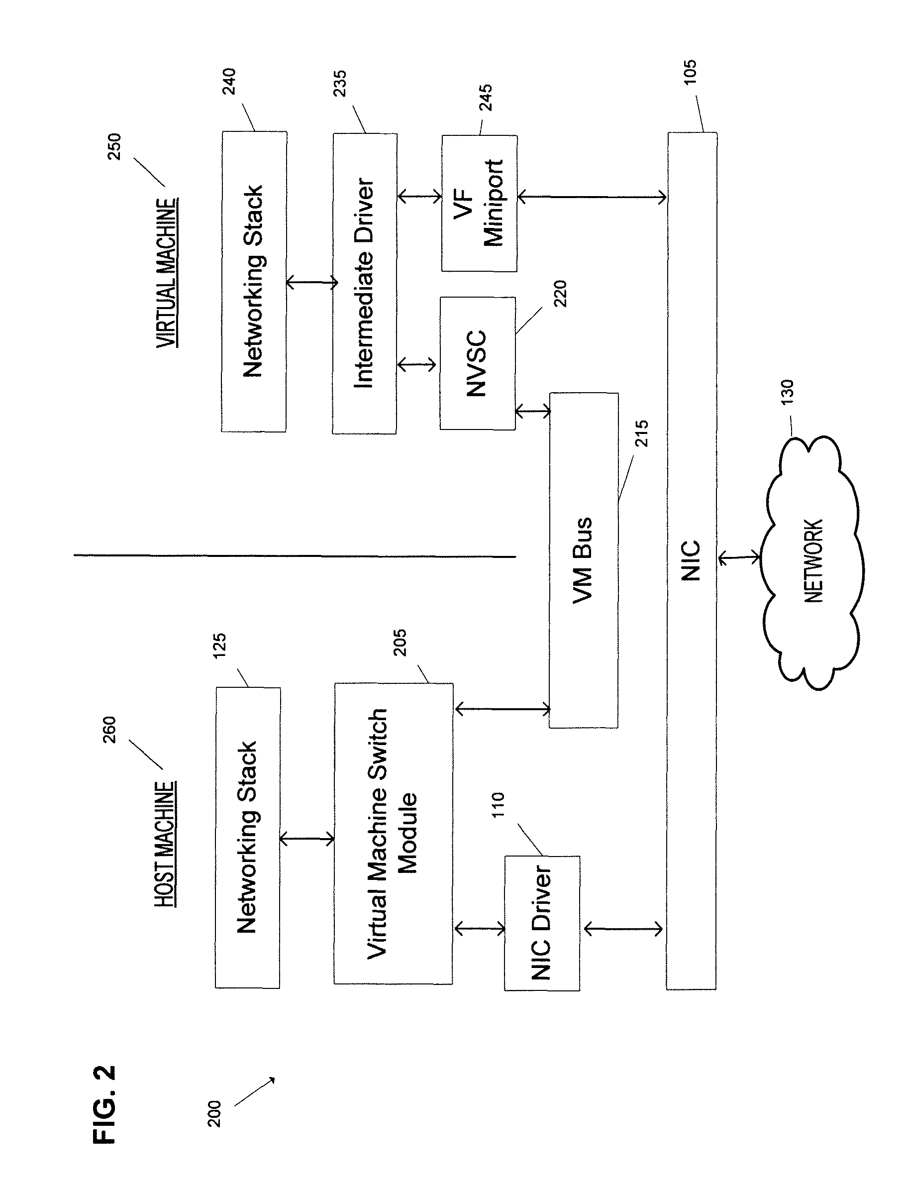
[0012]FIG. 2 illustrates why providing a failover capability can complicate networking on a computer employing virtualization. FIG. 2 depicts example components in a computer 200 that employs virtualization. In the example shown, computer 200 includes host machine 260 and virtual machine 250. Although only one virtual machine is depicted in FIG. 2, it should be appreciated that any number of virtual machines may be implemented ...


PUM


Abstract

Some embodiments of the invention provide a failover capability in a computer system that employs multiple paths to transfer information between virtual machines and a network, without introducing a driver component to provide this capability. For example, some embodiments of the invention provide a networking virtual switch client capable of direct communication between a networking stack implemented by a virtual machine operating system and components comprising either a direct path or a synthetic path to a network interface controller coupled to a network. The networking virtual switch client may be capable of determining which of the paths to employ for a given communication, such as by determining that a synthetic path should be employed if a direct path is not available.

Description

BACKGROUND[0001]An operating system comprises software, including programs and data, that runs on a computer to manage the computer's resources, and to provide services used during execution of application programs on the computer. Many conventional operating systems also provide a computer with the capability to communicate with one or more other devices via a network. For example, many conventional operating systems support one or more networking protocols (e.g., the Transport Control Protocol / Internet Protocol, or TCP / IP, protocol) through implementation of a “network stack.” Many operating systems also implement interfaces defining how various protocols make use of transport hardware (e.g., a network interface controller, or NIC). For example, certain of the WINDOWS® family of operating systems offered by Microsoft Corporation of Redmond, Wash. implement the Network Driver Interface Specification, or NDIS, to manage how transport protocol software employs NIC hardware.[0002]This...

Claims


Application Information

Patent Timeline
Patent Type & Authority Patents(United States)
IPC IPC(8): G06F15/16G06F9/06G06F11/14G06F11/20
CPCG06F9/06G06F11/1484G06F11/2012G06F11/2005G06F11/2007G06F9/45533
Inventor BONACI, DAVORMUNDKUR, SAMBHRAMA
Owner MICROSOFT TECH LICENSING LLC
Learn More