
Electric deicing device for propfan-type propeller blades

Active Publication Date: 2014-09-23
AIRBUS OPERATIONS (SAS)
View PDF12 Cites 2 Cited by
  • Summary
  • Abstract
  • Description
  • Claims
  • Application Information

AI Technical Summary

Benefits of technology

The invention proposes a device to deice / anti-ice blades for propfan-type propulsion units. The device avoids drawbacks and maximizes energy yield in real-time. The technical effect is improved efficiency and reliability of propulsion units.

Problems solved by technology

During the various phases of flight, particularly on the ground, at take-off, climbing or landing, aircraft are regularly subjected to icing atmospheric conditions (cold surface+ambient humidity), which cause ice deposits to be created on various parts of the fuselage.
These ice deposits modify the aircraft's aerodynamic performance, increase its mass and reduce its maneuverability.
It is obvious that similar problems of fighting icing by anti-icing or deicing occur for the propeller blades in the case of propeller-driven airplanes.
This mode of deicing at regular intervals reduces the electrical power needed and the size of the generator.
One of the main drawbacks of these rotating contact systems is linked to the speed of the brushes in relation to the moving track, this speed being in general close to one hundred meters per second and depending naturally on the diameter of the annular track and on the speed of rotation of this part.
The consequence of this for all these rotating contact systems is rapid wear of the brushes, leading to reduced performance and a requirement for frequent and costly maintenance.
The absence of lubrication for these brushes (for reasons of complexity) also contributes to reducing this lifespan significantly.
In the case of the front propeller of a propfan, the diameter of the turbomachine's core leads to a relative speed of the moving part in relation to the stationary part of the order of four hundred meters per second, which makes systems using brushes and a moving track unusable in practice, as this exceeds the specifications of devices available on the market.
Lastly, propfans are characterized by the high temperature of the exhaust flow they generate, about 800° C. at the outlet; this gas flow passes between the propulsion unit's shaft and the two propellers and makes it difficult to install materials that may suffer in high-temperature conditions.

Method used


Image

  • Electric deicing device for propfan-type propeller blades
  • Electric deicing device for propfan-type propeller blades
  • Electric deicing device for propfan-type propeller blades

Examples


Embodiment Construction

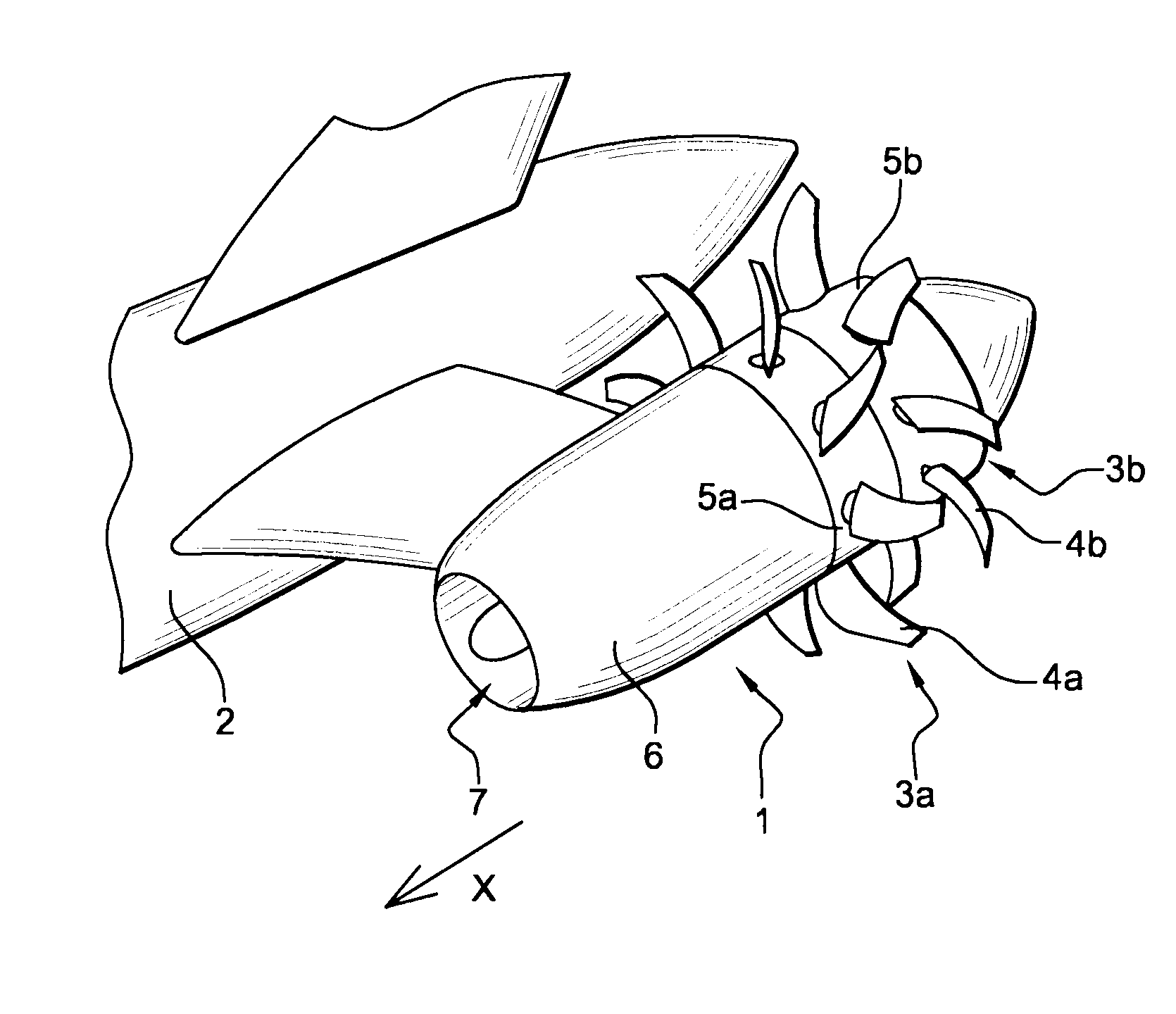
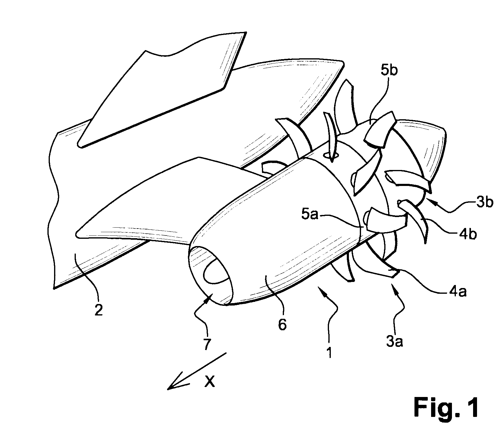
[0039]The invention is destined to be used in an airplane propulsion unit 1, for example of the type called “propfan”, as shown in FIG. 1. Such propulsion units are envisaged for future aircraft. In the example of implementation illustrated here, two propfan propulsion units 1 are attached by engine pylons, on both sides of the rear part of an aircraft fuselage 2.

[0040]Each propfan propulsion unit 1 comprises here two counter-rotating rotors 3a, 3b each comprising a set of blades 4a, 4b, which are equidistant and arranged at the rear of the propulsion unit 1. The blades 4a, 4b of each rotor 3a, 3b protrude from an annular crown 5a, 5b, which is mobile with this rotor, the outer surface of which is located in the continuity of the outer envelope 6 of the propulsion unit.

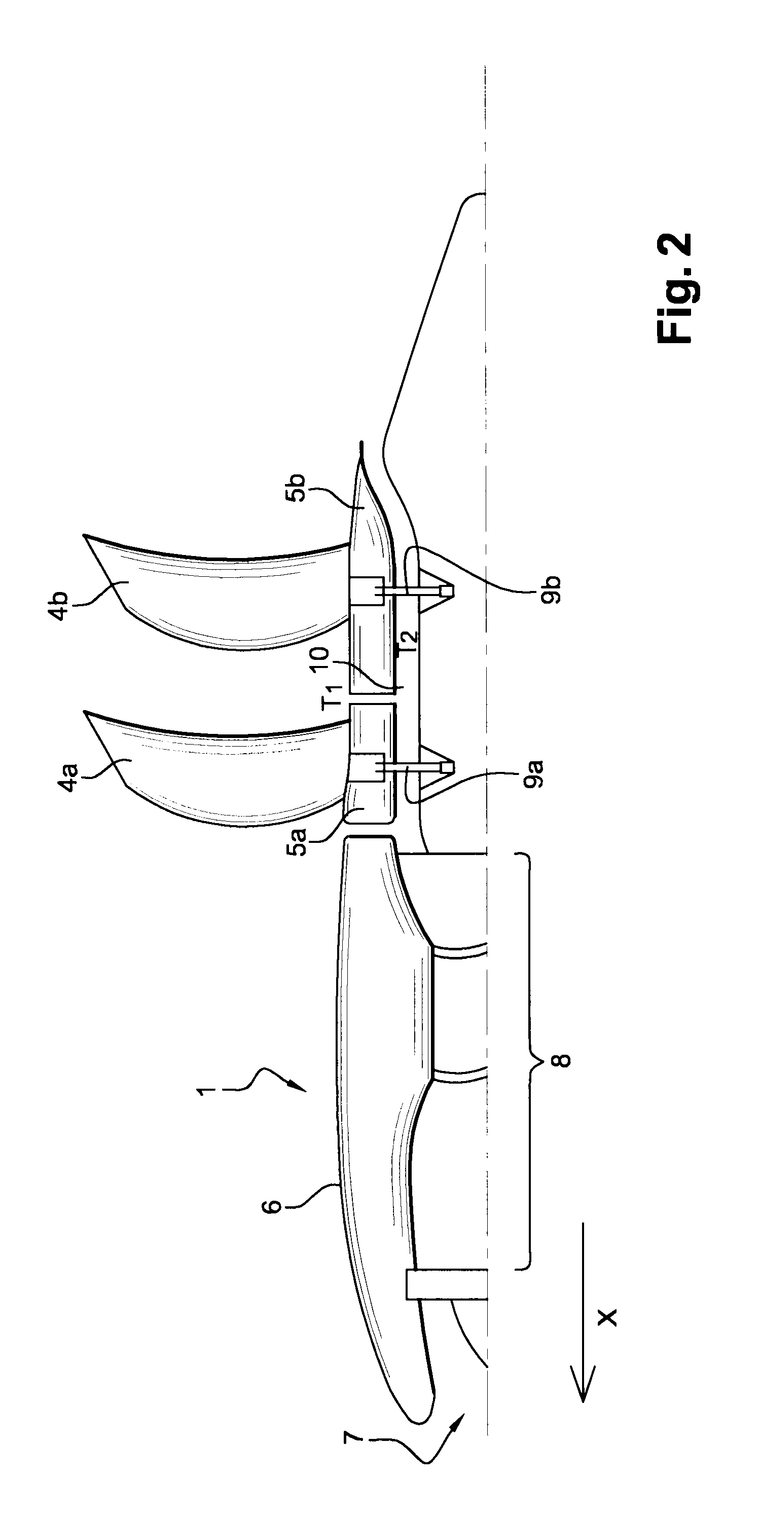
[0041]As shown schematically in FIG. 2 the propfan propulsion unit 1 comprises an air inlet 7 that supplies a turbomachine 8. This turbomachine 8 comprises an axial portion driven in rotation when the turbomachine is ...


PUM


Abstract

A deicing device for propfan-type aircraft propulsion unit blades, wherein the propulsion unit includes a turbomachine that drives in rotation at least one rotor including a plurality of blades arranged around an annular crown moving with the blades, which forms with its outer wall part of the outer envelope of the propulsion unit, the outer envelope being subjected to atmospheric conditions outside the propulsion unit, the turbomachine generating a flow of hot gases that exit via an annular hot vein, which is concentric with the moving annular crown, and defined for part of its surface by an inner wall of the moving annular crown. The deicing device includes: a mechanism transforming thermal energy into electrical energy, within the moving annular part; a mechanism transferring the generated electrical energy towards the rotor blades; and a mechanism transforming the electrical energy into thermal energy onto at least a part of the surface of the blades.

Description

BACKGROUND OF THE INVENTION[0001]The present invention falls within the field of aeronautical equipment. It concerns more specifically deicing devices. In this case, it relates in particular to the problem of deicing propeller blades.[0002]During the various phases of flight, particularly on the ground, at take-off, climbing or landing, aircraft are regularly subjected to icing atmospheric conditions (cold surface+ambient humidity), which cause ice deposits to be created on various parts of the fuselage. These ice deposits modify the aircraft's aerodynamic performance, increase its mass and reduce its maneuverability.[0003]Various anti-icing devices (that prevent ice forming on a surface of the aircraft) and deicing devices (that detach pieces of ice once they have formed) have been developed over decades and are already known to experts. For example, for the leading edges of wings, they use heating resistors that cause the ice to melt and to break into pieces removed by the airflow...

Claims


Application Information

Patent Timeline
IPC IPC(8): B60L1/02B64C11/48B64D15/12B64D27/02
CPCB64D15/12B64C11/48B64D2027/026Y02T50/66F28D15/02Y02T50/60B64D27/026
Inventor BULIN, GUILLAUMEPERRET, SEVERINE
Owner AIRBUS OPERATIONS (SAS)
Learn More