Supercharge Your Innovation With Domain-Expert AI Agents!

Apparatus and techniques for controlling ion angular spread

a technology of ion angular spread and ion implantation, which is applied in the field of beam angle uniformity control of ion implantation apparatus, can solve the problems of certain non-uniformities and achieve the effect of reducing the number of ion implantations

Active Publication Date: 2014-09-23
VARIAN SEMICON EQUIP ASSOC INC
View PDF10 Cites 3 Cited by
  • Summary
  • Abstract
  • Description
  • Claims
  • Application Information

AI Technical Summary

Benefits of technology

The patent describes an ion implantation system that uses an electrostatic scanner to scan an ion beam. The system also includes a magnetic collimator to bend the beam in a curve within a plane. The scanner generates an electrostatic field between two plates to focus the beam in a vertical direction. The system achieves more divergent vertical focusing along the outer curve of the beam than the inner curve. The technical effect of this system is improved precision and accuracy in ion implantation.

Problems solved by technology

The patent text discusses the problem of non-uniformity during the implant process for semiconductor electronics and solar cells. Non-uniformity can be caused by the ion beam used for doping, which can result in differences in the angle at which ions impact the substrate. This can lead to issues with the quality and consistency of the implant process. The technical problem addressed by the patent is how to improve the uniformity of the ion beam during the implant process.

Method used


Image

  • Apparatus and techniques for controlling ion angular spread
  • Apparatus and techniques for controlling ion angular spread
  • Apparatus and techniques for controlling ion angular spread

Examples


Embodiment Construction

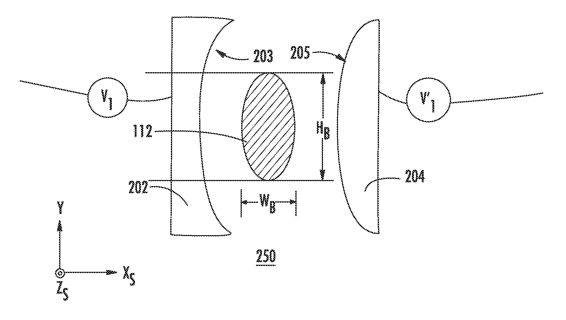
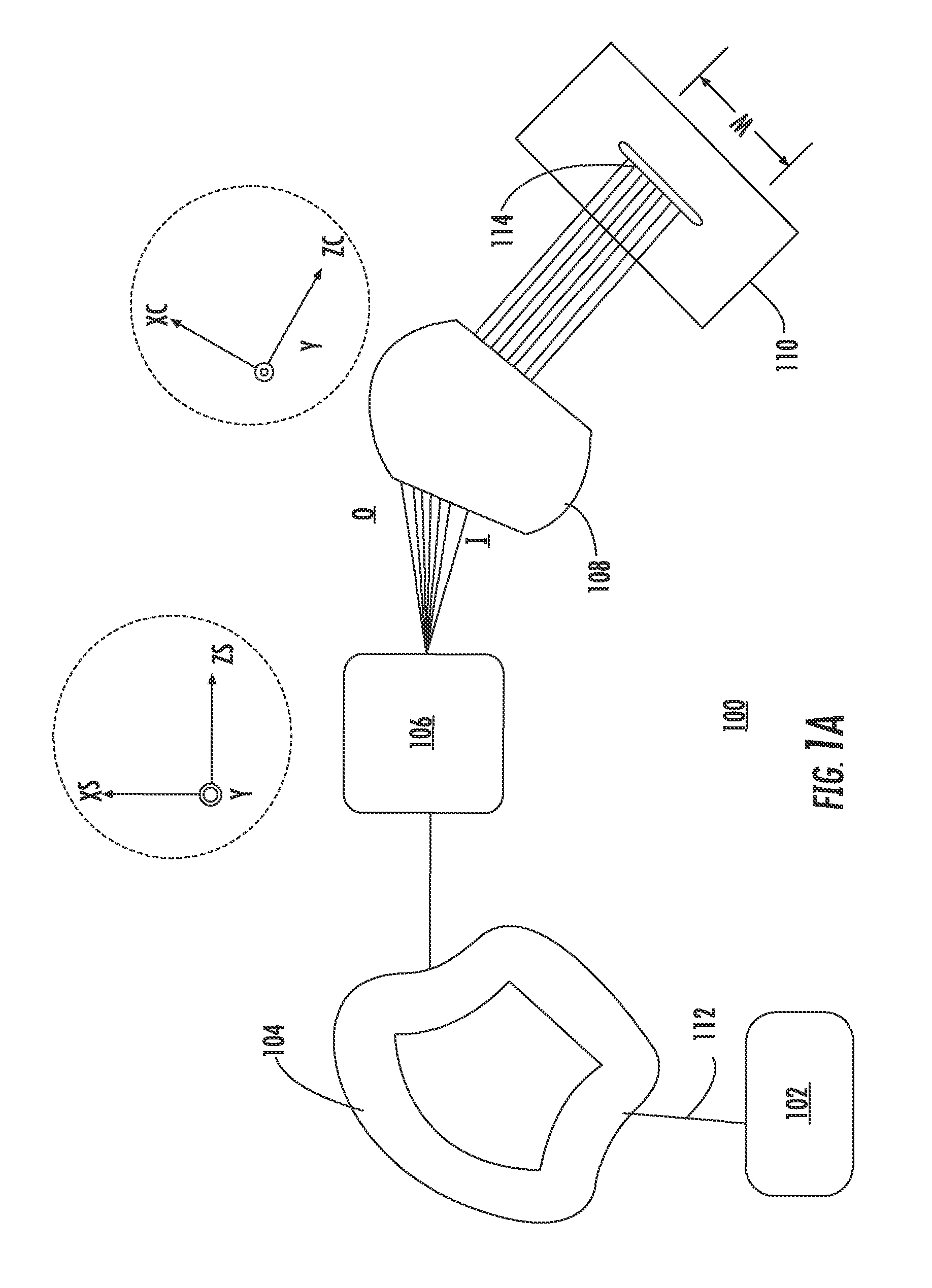
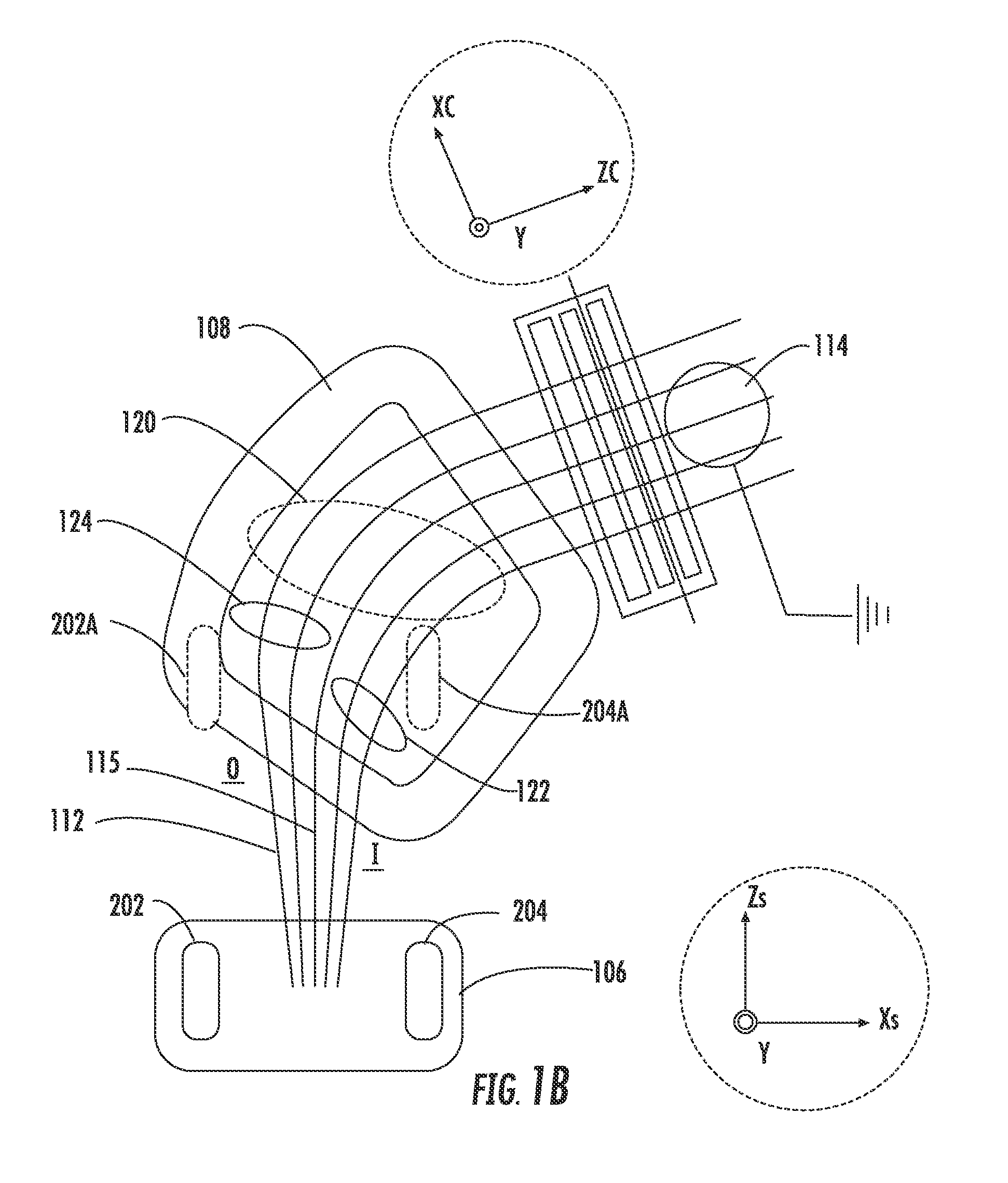
[0018]The embodiments described herein provide apparatus and methods for controlling an ion beam in an ion implantation system. Examples of an ion implantation system include a beamline ion implantation system. The ion implantation systems covered by the present-embodiments include those that generate “spot ion beams” that have a cross-section that has the general shape of a spot. In the present embodiments, a novel deflection system is provided to adjust beam properties of an ion beam passing therethrough. The novel deflection system in particular may form part of an electrostatic scanner and may be used to scan and shape the beam in a manner that compensates for nonuniformities induced by other beamline components. In various embodiments, as detailed below a set of curved electrostatic plate pairs is used in conjunction with a beam collimator such as a magnetic collimator to reduce non-uniformity in vertical angle spread of an ion beam as it is scanned across a substrate.

[0019]The...


PUM


Abstract

An electrostatic scanner to scan an ion beam in an ion implanter. The electrostatic scanner may include a first scan plate having a first inner surface that faces the ion beam, the first inner surface having a concave shape in a first plane that is perpendicular to a direction of propagation of the ion beam, and a second scan plate opposite the first scan plate separated by a gap to accept the ion beam the second scan plate having a second inner surface that faces the ion beam and a convex shape in the first plane, the first scan plate and second scan plate configured to generate an electrostatic field in the gap to scan the ion beam back and forth along a horizontal direction perpendicular to the direction of propagation of the ion beam.

Description


Claims


Application Information

Patent Timeline
Owner VARIAN SEMICON EQUIP ASSOC INC
Features
  • R&D
  • Intellectual Property
  • Life Sciences
  • Materials
  • Tech Scout
  • Unparalleled Data Quality
  • Higher Quality Content
  • 60% Fewer Hallucinations
Learn More