Crossed field device

a cross-field device and cross-field technology, applied in the field of devices, can solve the problems of cross-field devices not being able to produce high-frequency electromagnetic (em) emissions at elevated power levels, structures and features oftentimes cannot withstand electrical current, and certain technical challenges still exis

Active Publication Date: 2014-09-23
RGT UNIV OF MICHIGAN
View PDF6 Cites 6 Cited by
  • Summary
  • Abstract
  • Description
  • Claims
  • Application Information

AI Technical Summary

Problems solved by technology

Although crossed field devices, such as magnetrons and crossed field amplifiers, have been used in a variety of different applications ranging from microwave ovens to military radar equipment, certain technical challenges still exist.
For example, some crossed field devices are unable to produce high frequency electromagnetic (EM) emissions at elevated power levels.
Such structures and features oftentimes cannot withstand the electrical current and resulting heat that is required to generate the power levels needed.

Method used


Image

  • Crossed field device
  • Crossed field device
  • Crossed field device

Examples


Embodiment Construction

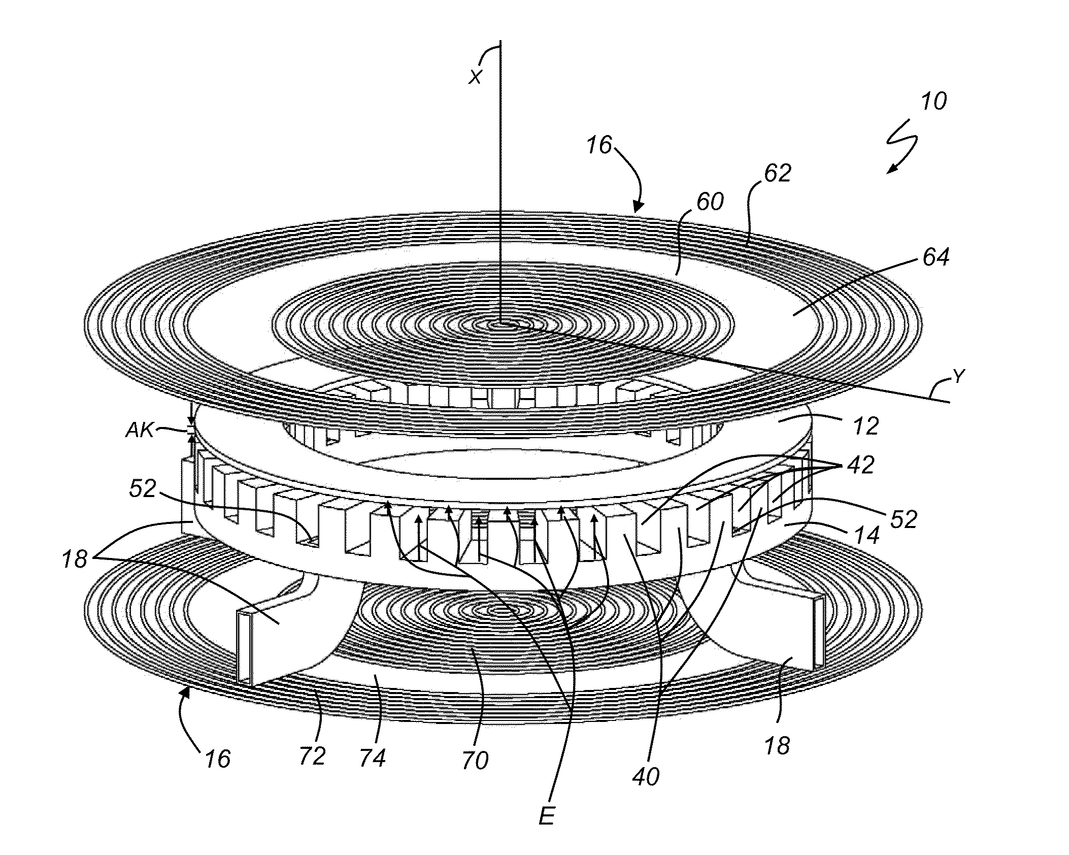
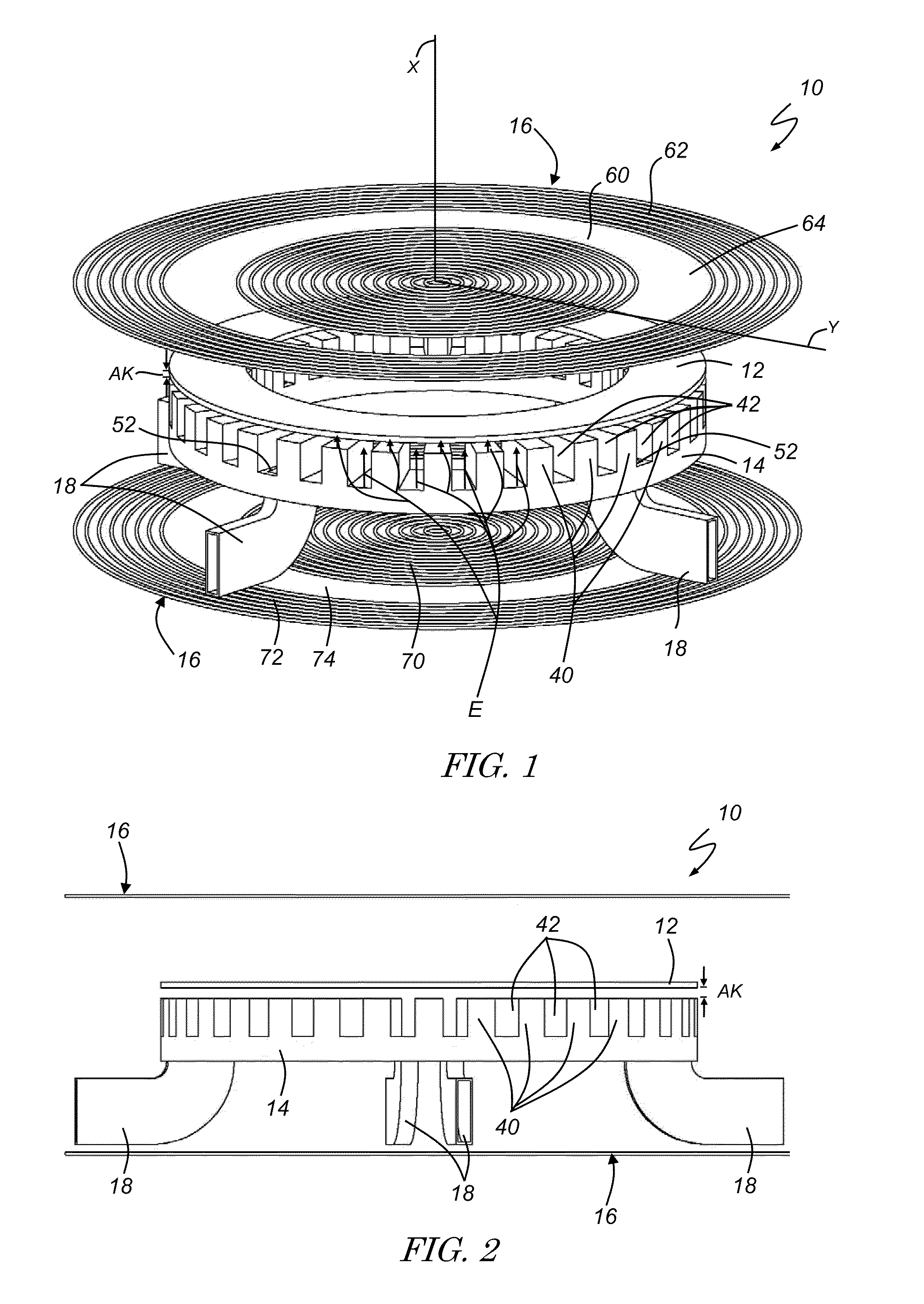
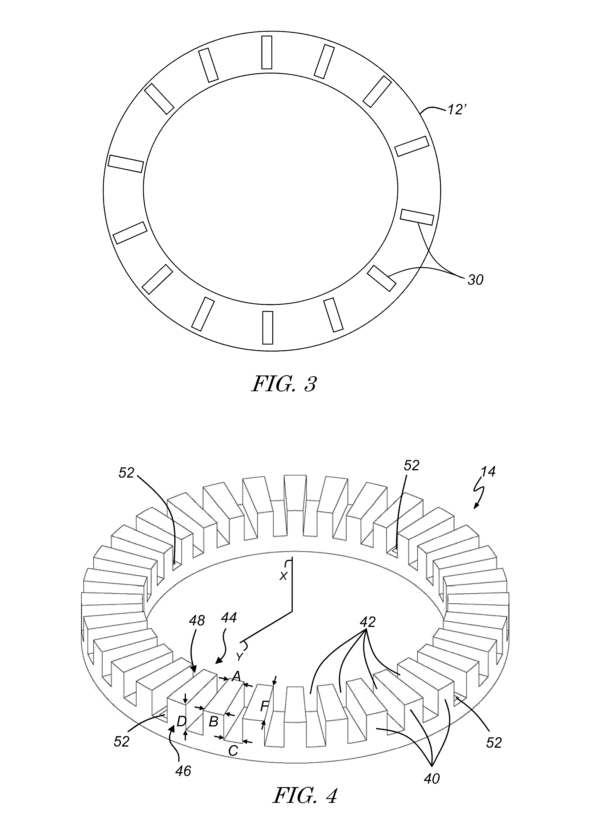
[0030]Crossed field devices, such as magnetrons and crossed field amplifiers, use electrons in electric and magnetic fields to generate electromagnetic (EM) emissions and may be employed in a number of different applications. For example, crossed field devices may be used in microwave ovens, radar systems, medical equipment, scientific instruments, communication systems, electronic counter measures, and certain lighting arrangements, to name a few examples. Although the following description is provided in the context of an exemplary magnetron, it should be appreciated that it also applies to other crossed field devices like crossed field amplifiers.

[0031]The term “planar,” as used herein in the context of an anode, cathode or other element of a crossed field device, broadly refers to a component having a thickness in the axial direction that is less than or equal to one wavelength (λ) of the electromagnetic (EM) emissions produced by the crossed field device. It should be appreciat...


PUM


Abstract

A crossed field device, such as a magnetron or crossed field amplifier, that includes a cathode, an anode, one or more magnetic elements, and one or more extraction elements. In one embodiment, the crossed field device includes an annular cathode and anode that are axially spaced from one another such that the device produces an axial electric (E) field and a radial magnetic (B) field. In another embodiment, the crossed field device includes an oval-shaped cathode and anode that are radially spaced from one another such that the device produces a radial electric (E) field and an axial magnetic (B) field. The crossed field device may produce electromagnetic (EM) emissions having a frequency ranging from megahertz (MHz) to terahertz (THz), and may be used in one of a number of different applications.

Description

REFERENCE TO RELATED APPLICATIONS[0001]This application claims the benefit of U.S. Provisional Ser. No. 61 / 235,812 filed Aug. 21, 2009, the entire contents of which are incorporated herein.[0002]This invention was made with government support under Contract Nos. FA9550-05-1-0087 and FA9550-10-1-0104 awarded by The Air Force Office of Scientific Research. The government has certain rights in the invention.TECHNICAL FIELD[0003]This invention generally relates to devices that produce electromagnetic (EM) emissions and, more particularly, to crossed field devices that produce such emissions.BACKGROUND OF THE INVENTION[0004]Although crossed field devices, such as magnetrons and crossed field amplifiers, have been used in a variety of different applications ranging from microwave ovens to military radar equipment, certain technical challenges still exist.[0005]For example, some crossed field devices are unable to produce high frequency electromagnetic (EM) emissions at elevated power leve...

Claims


Application Information

Patent Timeline
Patent Type & Authority Patents(United States)
IPC IPC(8): H05H7/00H01J23/02H01J25/42
CPCH01J25/42H01J23/02
Inventor GILGENBACH, RONALD M.LAU, YUE-YINGFRENCH, DAVID M.HOFF, BRAD W.LUGINSLAND, JOHNFRANZI, MATTHEW
Owner RGT UNIV OF MICHIGAN
Why Eureka
Try Eureka