
Videoconferencing system having adjunct camera for auto-framing and tracking

a videoconferencing system and camera technology, applied in the field of videoconferencing systems, can solve the problems of not being able to adjust, the far-end participants may lose much of the value of the video captured by the camera, and the far-end participants cannot see the facial expressions of the near-end participants, so as to achieve the effect of convenient coordination

Active Publication Date: 2014-09-23
HEWLETT PACKARD DEV CO LP
View PDF31 Cites 76 Cited by
  • Summary
  • Abstract
  • Description
  • Claims
  • Application Information

AI Technical Summary

Benefits of technology

[0013]In a videoconference apparatus and method, a stationary or fixed view of an environment is obtained with a stationary or fixed camera of the apparatus and is coordinated with an adjustable view of the environment obtained with a second, adjustable camera. In one arrangement, the stationary camera is a web camera, while the adjustable camera is a controllable camera, such as a pan-tilt-zoom camera, although other arrangements can be used. These two cameras are preferably co-located in or on a shared housing location. Being co-located, the cameras share the same view angle of the environment, and their two views can be more readily aligned for coordination.
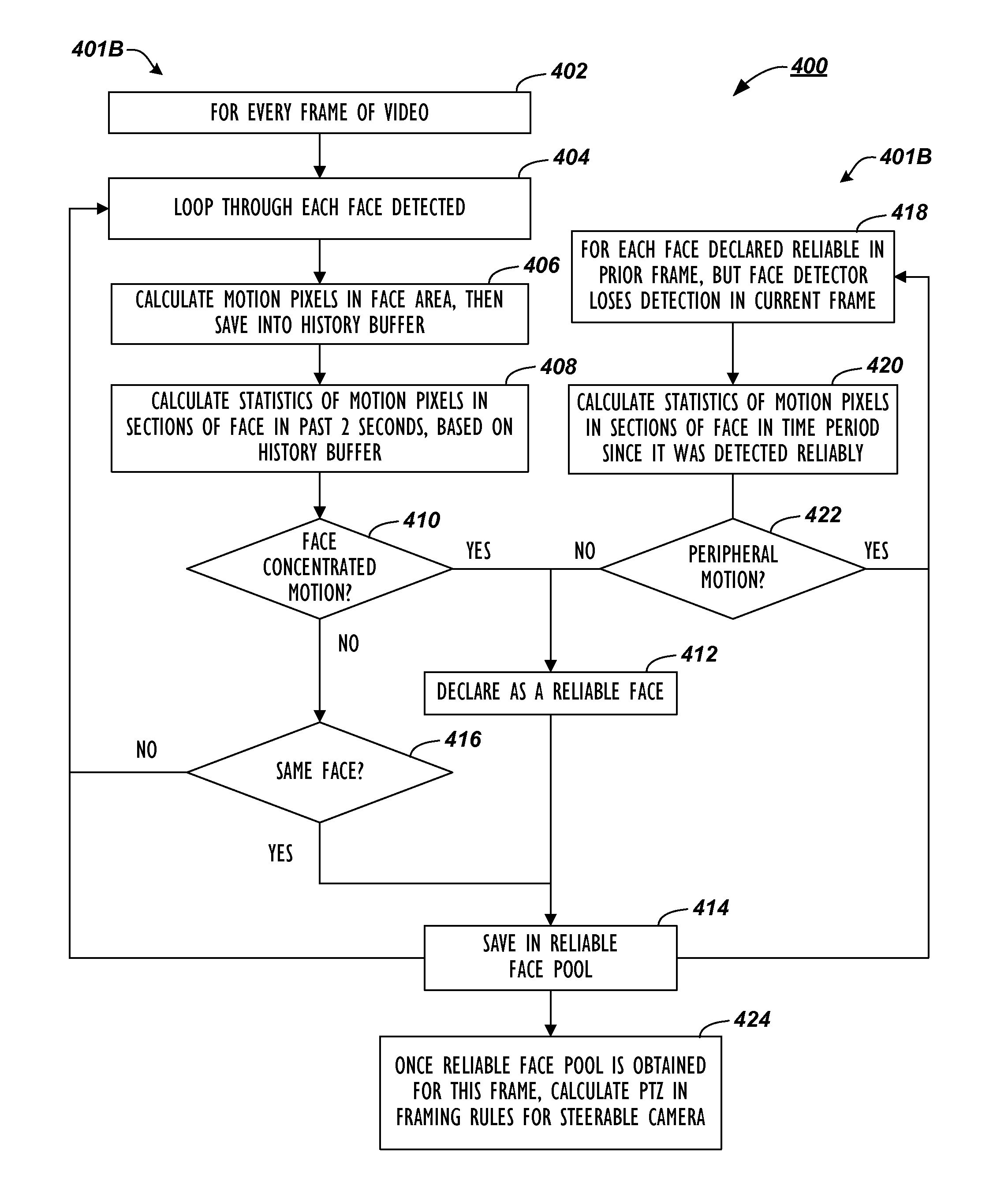
[0016]For example, the area of interest for a detected face can include an on-face section at the location of the detected face. If motion is detected at this on-face section for a given detected face, then the apparatus can indicate the given face as reliable. Rather than just disregarding the given detected face when motion detection fails to find motion in the on-face section, the apparatus can instead determine whether the location of the given face was previously detected and indicated as reliable. If so, then the face detection can still be reliable even though motion has not been detected in the on-face section.

Problems solved by technology

Unfortunately, due to the difficulty of performing these adjustments, the camera may often be set to a fixed, wide-angle view of the entire room and may not be adjusted.
If this is the case, far-end participants may lose much of the value from the video captured by the camera because the size of the near-end participants displayed at the far-end may be too small.
In some cases, the far-end participants cannot see the facial expressions of the near-end participants and may have difficulty determining who is actually speaking.
These problems give the videoconference an awkward feel and make it hard for the participants to have a productive meeting.
As expected, manually directing the camera can be cubersome even when a remote control is used.
Although the voice-tracking camera is very useful, it can still encounter some problems.
When a speaker turns away from the microphones, for example, the voice-tracking camera may lose track of the speaker.
Additionally, a very reverberant environment can cause the voice-tracking camera to direct at a reflection point rather than at an actual sound source of a person speaking.
As can be seen above, systems that use voice tracking and face detection may require complex processing and hardware to control a camera during a videoconference.
Moreover, such systems can have practical limitations.
This is so because such systems require a sufficient period of time for training to operate properly.
Yet, requiring manual initiation of the automated functions can cause problems when people walk in or out of a room during a meeting.
For example, the automated control of the camera fails when a participant turns his head away from the camera, which can happen quite often in a video conference.

Method used


Image

  • Videoconferencing system having adjunct camera for auto-framing and tracking
  • Videoconferencing system having adjunct camera for auto-framing and tracking
  • Videoconferencing system having adjunct camera for auto-framing and tracking

Examples


Embodiment Construction

[0034]A. Videoconferencing Endpoint

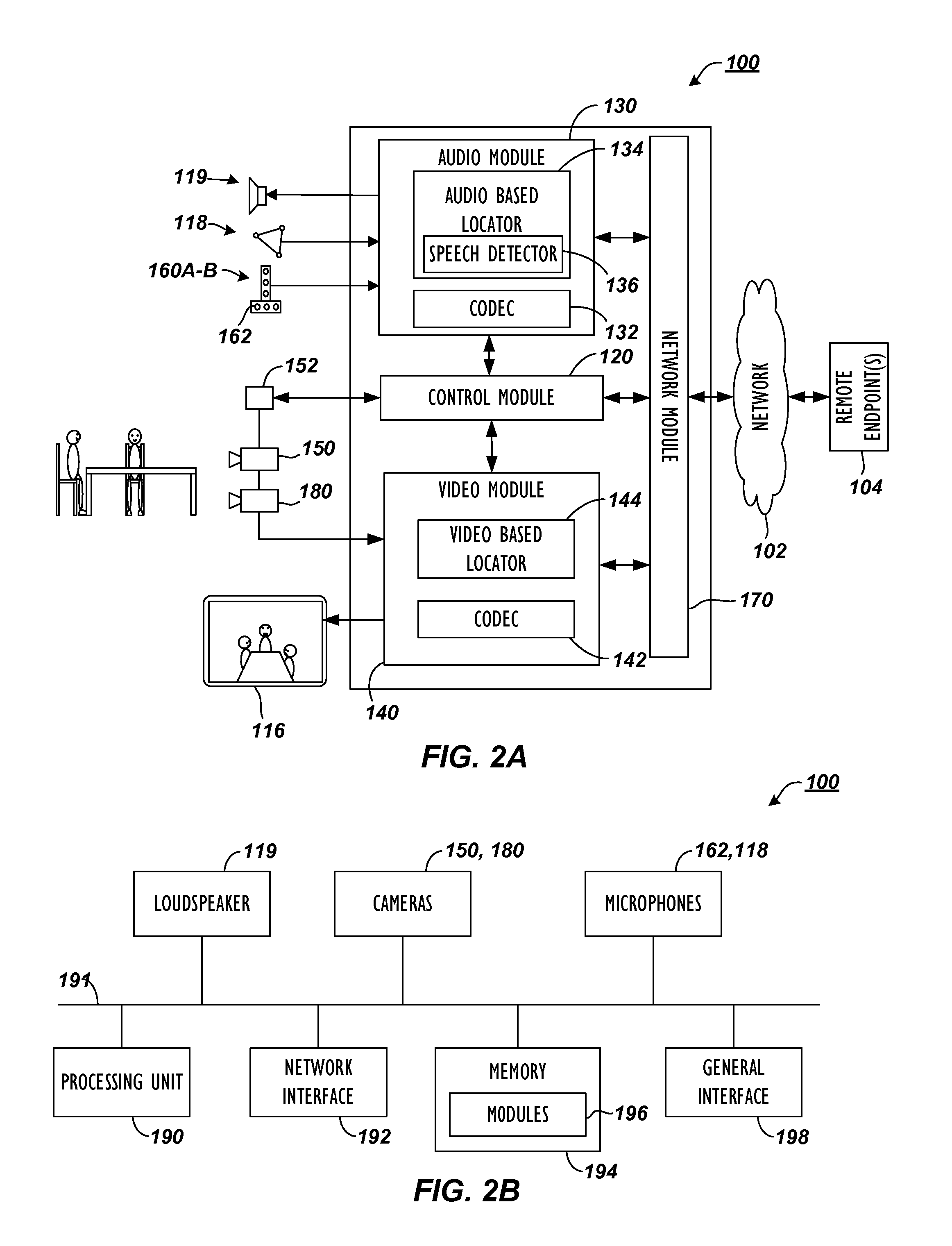
[0035]A videoconferencing apparatus or endpoint 100 in FIG. 2A communicates with one or more remote endpoints 104 over a network 102. Among some common components, the endpoint 100 has an audio module 130 with an audio codec 132 and has a video module 140 with a video codec 142. These modules 130 / 140 operatively couple to a control module 120 and a network module 170.

[0036]During a videoconference, a main camera 150 captures video and provides the captured video to the video module 140 and codec 142 for processing. Additionally, one or more microphones 118 capture audio and provide the audio to the audio module 130 and codec 132 for processing. These microphones 118 can be table or ceiling microphones or part of a microphone pod or the like, and the endpoint 100 uses the audio captured with these microphones 118 primarily for the conference audio.

[0037]Separately, if available for the endpoint 100, microphone arrays 160A-B having orthogonally arran...


PUM


Abstract

A videoconference apparatus and method coordinates a stationary view obtained with a stationary camera to an adjustable view obtained with an adjustable camera. The stationary camera can be a web camera, while the adjustable camera can be a pan-tilt-zoom camera. As the stationary camera obtains video, faces of participants are detected, and a boundary in the view is determined to contain the detected faces. Absence and presences of motion associated with the detected face is used to verify whether a face is reliable. To then capture and output video of the participants for the videoconference, the view of the adjustable camera is adjusted to a framed view based on the determined boundary. In the end, active video captured in the framed view with the adjustable camera can be sent to a far-end for the videoconference.

Description

CROSS-REFERENCE TO RELATED APPLICATIONS[0001]This is a continuation-in-part of U.S. application Ser. No. 12 / 782,137, filed 18-May-2010, which has been incorporated herein by reference in its entirety.BACKGROUND OF THE DISCLOSURE[0002]The camera for a videoconferencing system often has mechanical pan, tilt, and zoom control. Ideally, these controls should be continuously adjusted to achieve optimal video framing of the people in the room based on where they are seated and who is talking. Unfortunately, due to the difficulty of performing these adjustments, the camera may often be set to a fixed, wide-angle view of the entire room and may not be adjusted. If this is the case, far-end participants may lose much of the value from the video captured by the camera because the size of the near-end participants displayed at the far-end may be too small. In some cases, the far-end participants cannot see the facial expressions of the near-end participants and may have difficulty determining ...

Claims


Application Information

Patent Timeline
Patent Type & Authority Patents(United States)
IPC IPC(8): H04N7/14
CPCH04N7/15H04N5/232H04N5/23219H04N23/60H04N23/661H04N23/61H04N23/611H04N23/695
Inventor FENG, JINWEILIU, YIBOWANG, XIANGDONGCHU, PETER L.
Owner HEWLETT PACKARD DEV CO LP
Learn More