Fuel rail mount

a technology of fuel rails and mounting brackets, which is applied in the direction of machines/engines, manufacturing tools, washing machines, etc., can solve the problems of fuel rail vibration, undesirable noise, and undesirable noise, and achieve the effect of dampening vibrations

Active Publication Date: 2014-09-30
FORD GLOBAL TECH LLC
View PDF8 Cites 11 Cited by
  • Summary
  • Abstract
  • Description
  • Claims
  • Application Information

AI Technical Summary

Benefits of technology

[0006]The present invention is a fuel rail mounting assembly for attaching a fuel rail to an engine cylinder head. The mounting assembly includes a bracket attached to the fuel rail, a fastener for attaching the bracket to the cylinder head, and a metal shock absorber positioned between the bracket and the fastener to dampen vibrations between the fuel rail assembly and the cylinder head. Preferably, the metal shock absorber includes springs on either side of the bracket which are compressed between the cylinder head and a bolt which is threaded into the cylinder head. A sleeve may be provided between the cylinder head and one of the springs to properly position the bracket.

Problems solved by technology

High-pressure fuel pumps used in these systems commonly create pressure pulsations that can cause the fuel rail to vibrate.
This can create undesirable noise, especially noticeable at idle speeds.
Forces originating from the structure of fuel injectors can also cause undesirable noise, such as that caused by the energizing of magnetic solenoid valves and the impact of injector pins seating at injector closing.
However, it is difficult to control vibration frequencies with elastomeric components.
In addition, elastomers are subject to relatively rapid wear which can change the elastomeric characteristics.

Method used


Image

  • Fuel rail mount
  • Fuel rail mount
  • Fuel rail mount

Examples


Embodiment Construction

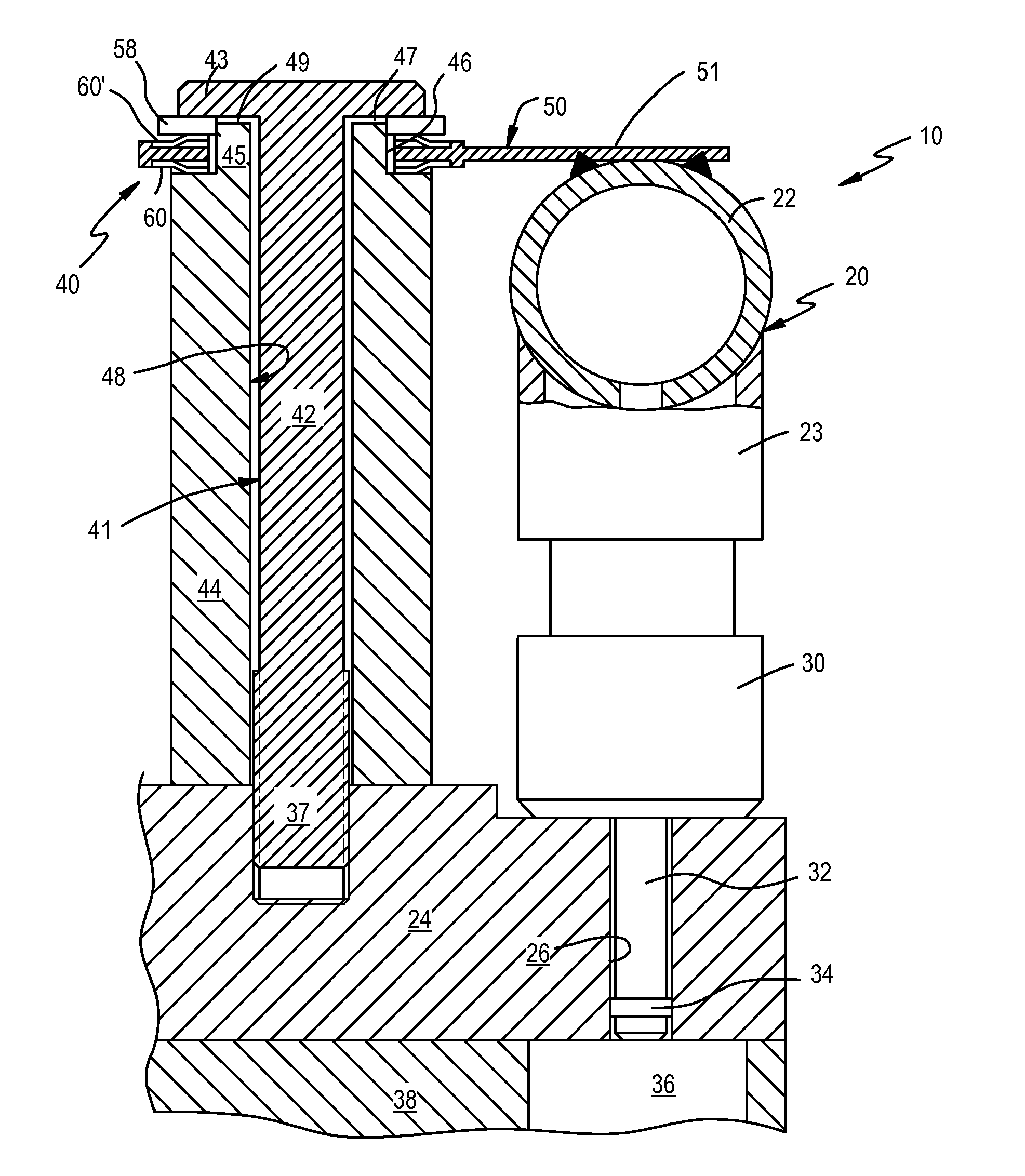
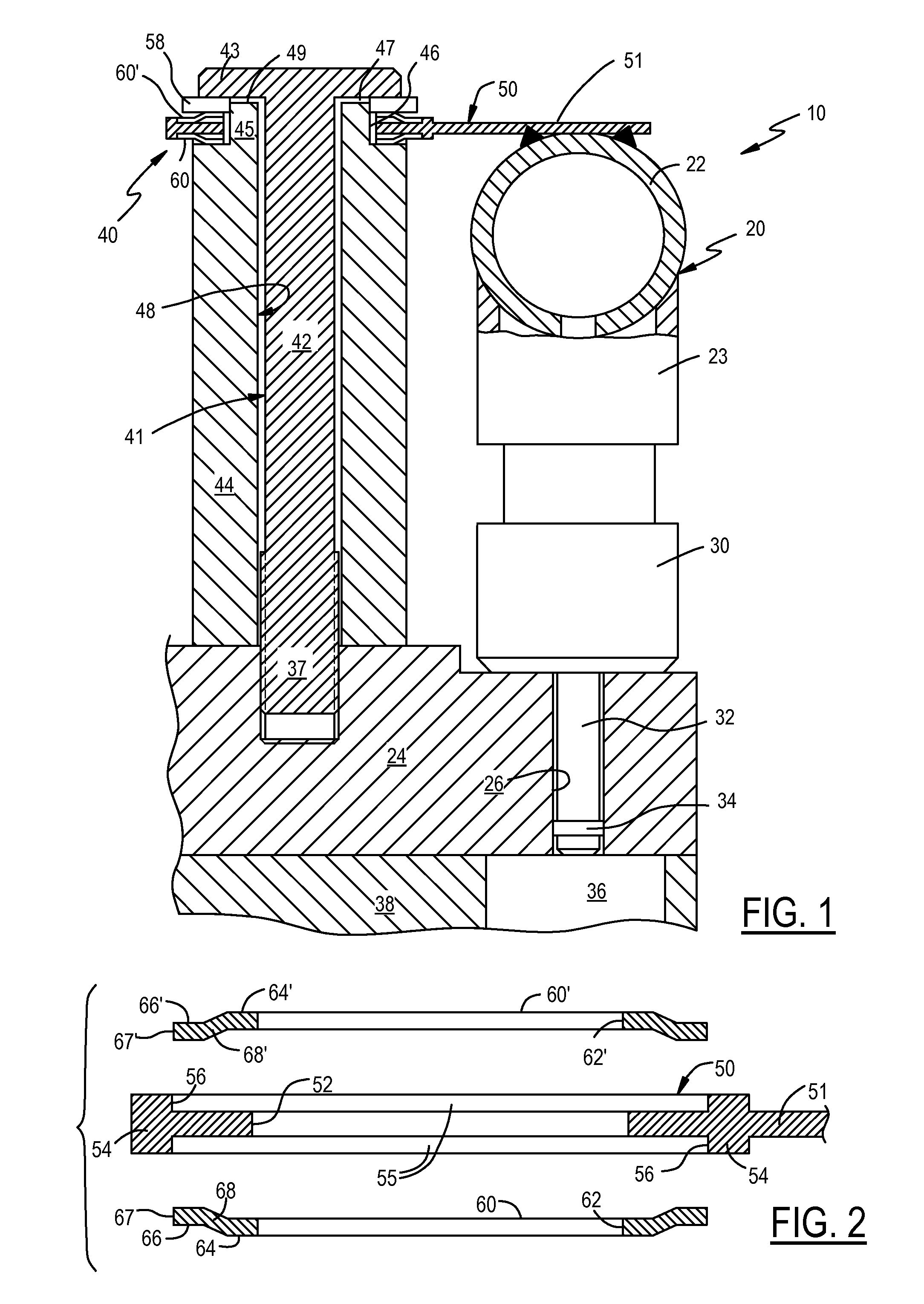
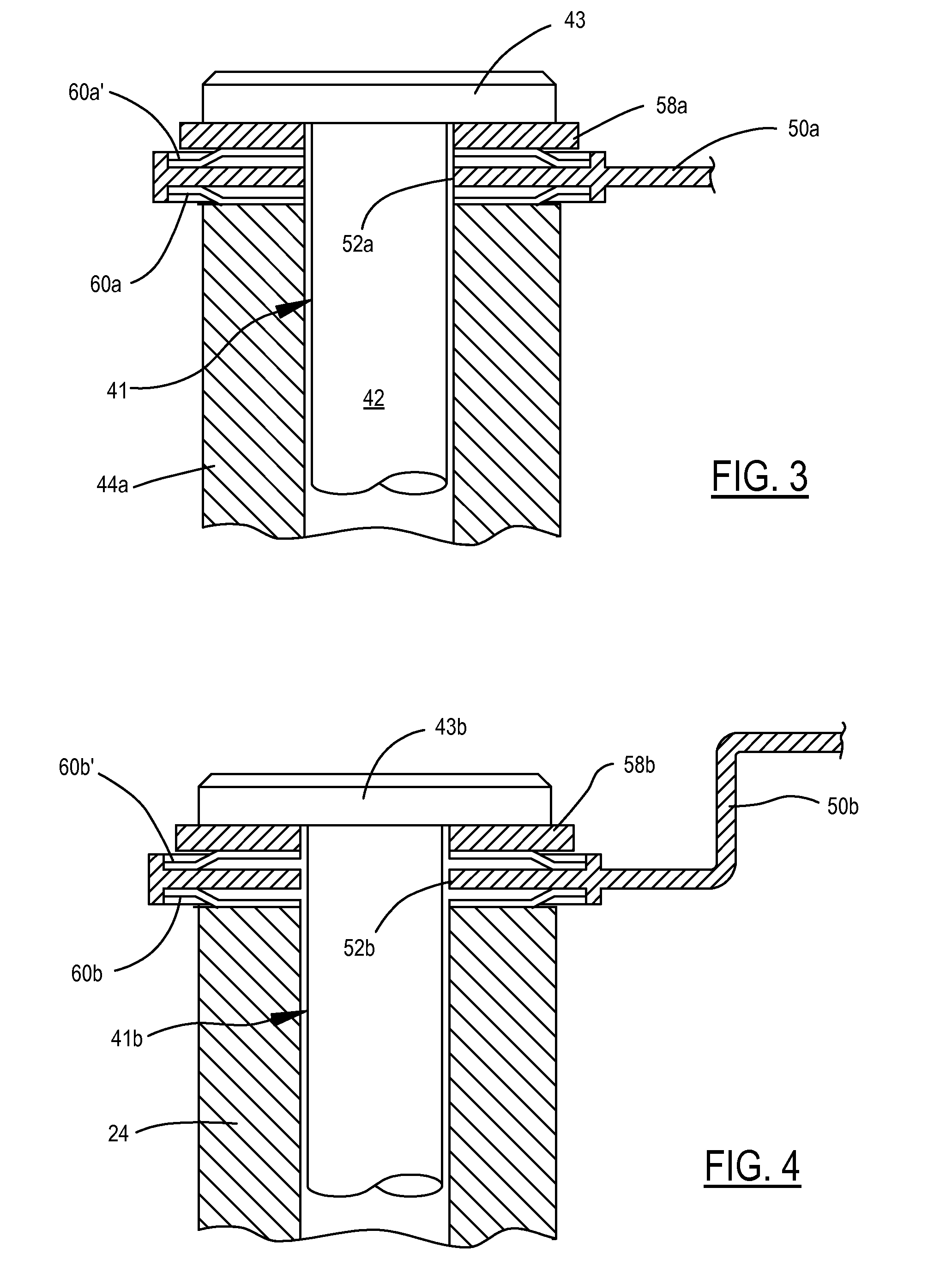
[0011]Referring to FIG. 1, a direct injection fuel injector system 10 includes a fuel rail assembly 20 including a fuel rail 22. A fuel rail cap 23 is welded or otherwise secured to the fuel rail 22. A fuel injector 30 is supported within the fuel rail cap 23. The injector 30 rests on an internal combustion engine cylinder head 24, but the invention is suitable for use with suspended injectors as well which may be in communication with a combustion chamber through an engine block or a cylinder head. An injector nozzle 32 extends into a bore 26 in the cylinder head 24 to provide fluid communication with a combustion chamber 36 in the engine block 38. An annular Teflon seal 34 fits snuggly around the nozzle 32 and sealingly engages the bore 26 to seal the combustion chamber 36. The seal 34 may experience limited axial sliding relative to the bore 26. The fuel rail 22 is welded to an arm 51 of a fuel rail bracket or clip 50 which supports the fuel rail assembly. Stainless steel is a pr...


PUM

PropertyMeasurementUnit
diameteraaaaaaaaaa
diameteraaaaaaaaaa
diameteraaaaaaaaaa

Abstract

An internal combustion engine direct injection fuel injector system includes a fuel rail which is welded to a fuel rail bracket. A fuel rail mounting sleeve has a flange and is bolted to the engine cylinder head. The bracket fits around the flange and is held in place by a steel washer and a pair of stepped isolator washers which are positioned in pockets formed on either side of the bracket. The isolator washers serve as springs which form a shock absorber between the bracket and cylinder head. Compression forces on the bracket and isolator washers are controlled by bolt tension.

Description

TECHNICAL FIELD[0001]The present invention relates to internal combustion engine fuel injection systems, and more particularly to the mounting of fuel rails of such systems.BACKGROUND OF THE INVENTION[0002]Direct injection is a common type of fuel injection system in which fuel is injected directly into the combustion chambers of an internal combustion engine by fuel injectors. A fuel rail, typically a tubular member, connects the fuel injectors to a fuel supply. Fuel injectors are typically mounted in fuel injector sockets in the fuel rail. Fuel rails in direct injection fuel systems are commonly mounted on the engine's cylinder head.[0003]Direct injection fuel rails experience significantly higher fuel pressures than other types of fuel injection systems. High-pressure fuel pumps used in these systems commonly create pressure pulsations that can cause the fuel rail to vibrate. This can create undesirable noise, especially noticeable at idle speeds. Forces originating from the stru...

Claims


Application Information

Patent Timeline
Patent Type & Authority Patents(United States)
IPC IPC(8): F02M61/14F02M61/18
CPCB23P19/00F02M55/025F16F15/073F02M2200/306F02M2200/857F02M2200/09F16B43/00F16F1/32Y10T29/53
Inventor SOLFERINO, VINCE P.ZENG, PAUL W.BROSTROM, PATRICK C.KAPUT, MICHAEL R.LEHTO, SCOTTAHMED, SYED M.
Owner FORD GLOBAL TECH LLC
Why Eureka
Try Eureka