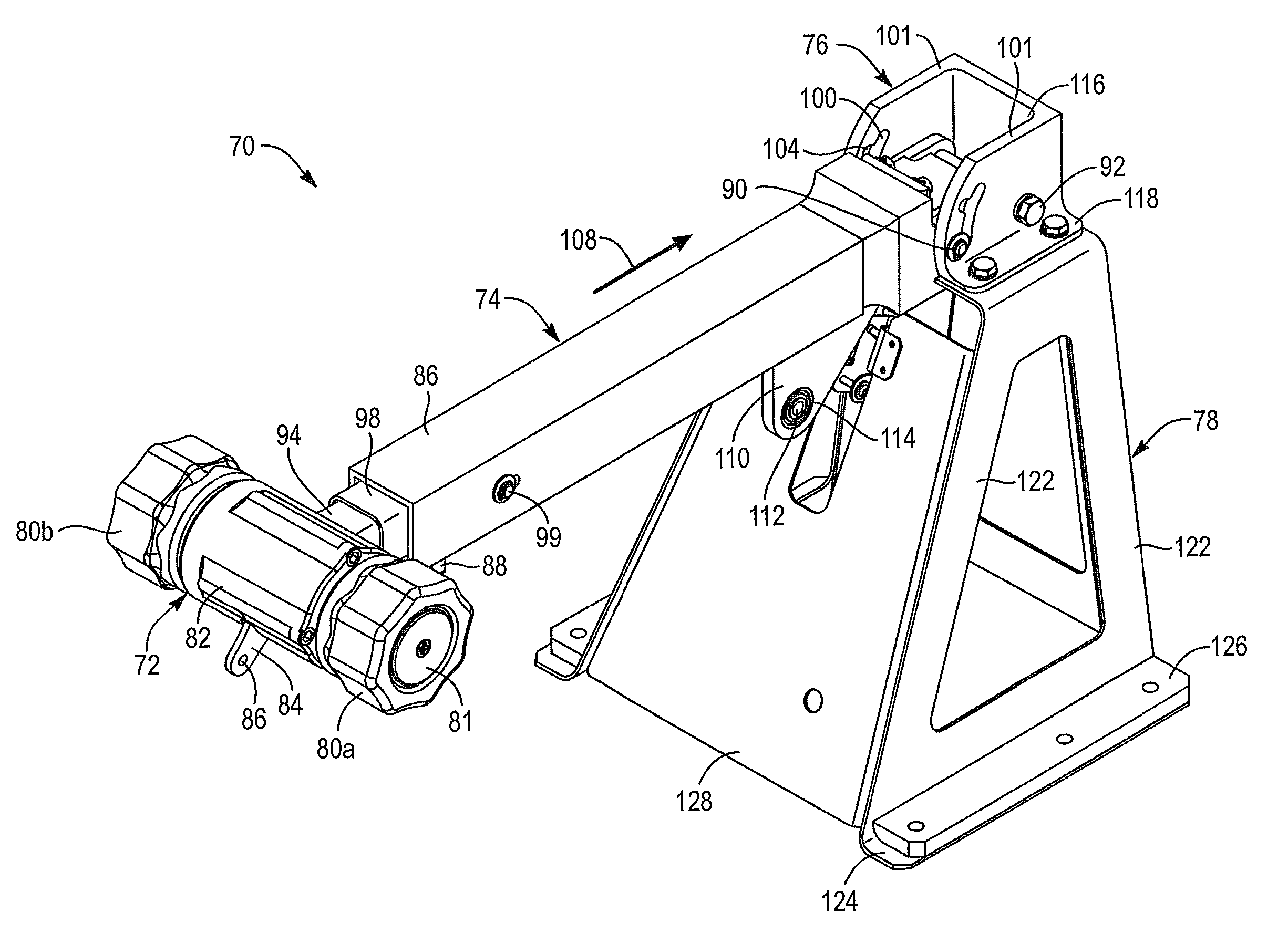
Two-place, collective pitch and throttle control

a collective pitch and throttle control technology, applied in the direction of mechanical control devices, process and machine control, instruments, etc., can solve the problems of stalling of the retracting blade, limited lift equalization due to flapping, and much more limited maximum flight speed of fixed wing aircra

Active Publication Date: 2014-09-30
SKYWORKS GLOBAL INC
View PDF21 Cites 41 Cited by
  • Summary
  • Abstract
  • Description
  • Claims
  • Application Information

AI Technical Summary

Problems solved by technology

Although rotating wing aircraft provide the significant advantage of vertical takeoff and landing (VTOL), they are much more limited in their maximum flight speed than are fixed wing aircraft.
However, lift equalization due to flapping is limited by a phenomenon known as “retreating blade stall.” As noted above, flapping of the rotor blades increases the angle of attack of the retreating blade.
However, at certain higher speeds, the increase in the blade angle of attack required to equalize lift on the advancing and retreating blades results in loss of lift (stalling) of the retreating blade.
A second limit on the speed of rotating wing aircraft is the drag at the tips of the rotor.
In autogyro aircraft, the tips of the advancing blades are also subject to this increased drag, even for flight speeds much lower than the speed of sound.
Nevertheless, the same drag increase occurs eventually.
For example, if the blade angle of attack is upward with respect to wind velocity, but wind is moving over the wing in a reverse direction, the blade may experience negative lift.

Method used


Image

  • Two-place, collective pitch and throttle control
  • Two-place, collective pitch and throttle control
  • Two-place, collective pitch and throttle control

Examples


Embodiment Construction

[0039]It will be readily understood that the components of the present invention, as generally described and illustrated in the drawings herein, could be arranged and designed in a wide variety of different configurations. Thus, the following more detailed description of the embodiments of the system and method of the present invention, as represented in the drawings, is not intended to limit the scope of the invention, as claimed, but is merely representative of various embodiments of the invention. The illustrated embodiments of the invention will be best understood by reference to the drawings, wherein like parts are designated by like numerals throughout.

[0040]This patent application hereby incorporates by reference U.S. Pat. No. 5,301,900 issued Apr. 12, 1994 to Groen et al., U.S. Pat. No. 1,947,901 issued Feb. 20, 1934 to J. De la Cierva, and U.S. Pat. No. 2,352,342 issued Jun. 27, 1944 to H. F. Pitcairn.

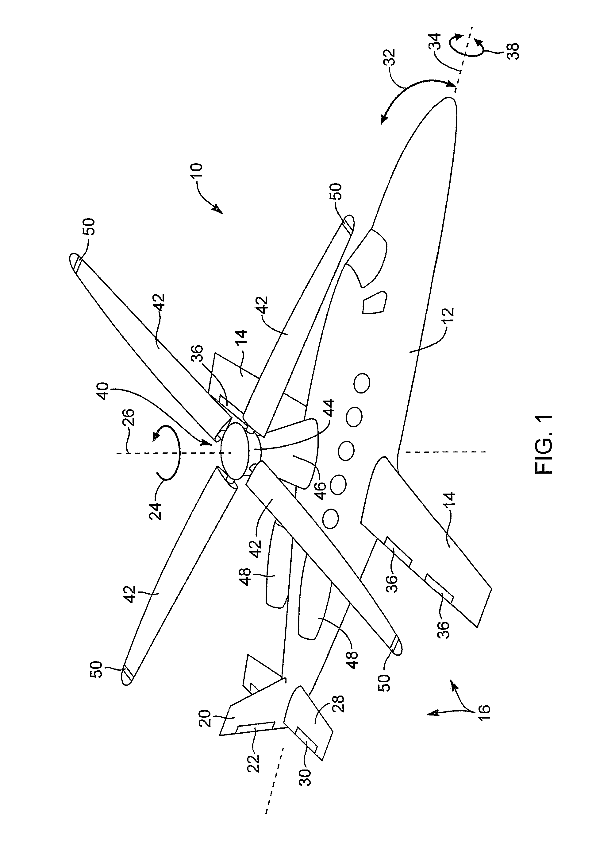
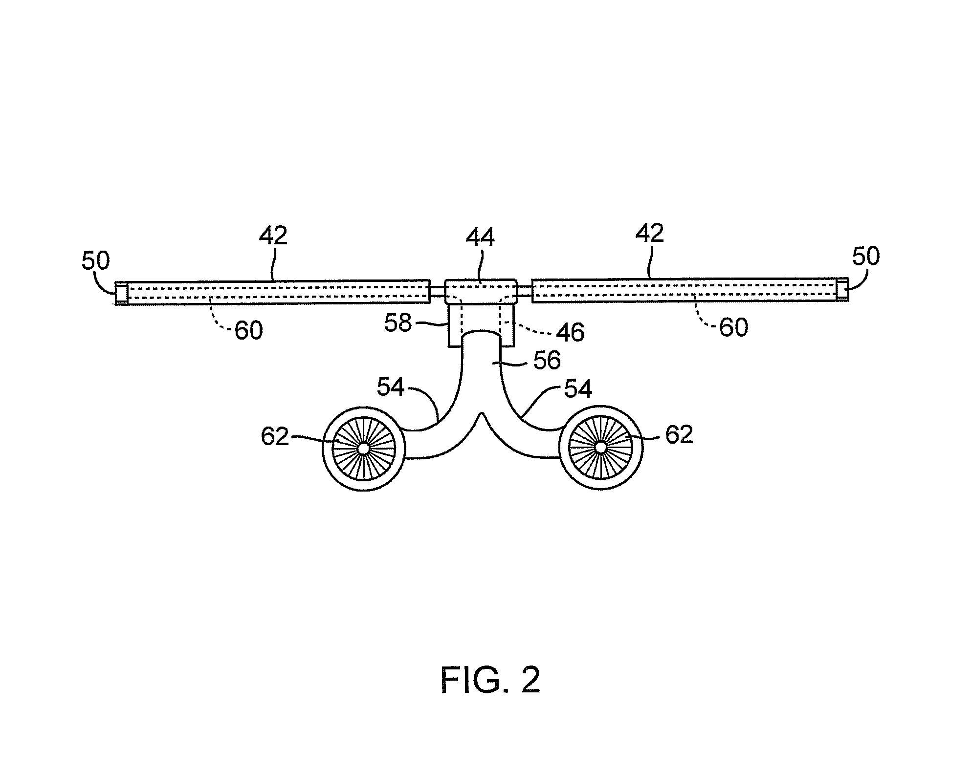
[0041]Referring to FIG. 1, an aircraft 10 includes a fuselage 12 defining...


PUM


Abstract

A heliplane operates with a fixed wing at high velocities, and particularly at high advance ratios, while using a rotary wing maintained in motion at all speeds. At high advance ratios, the rotor wing eventually may be rotated primarily to maintain its stability, rather than depending upon the majority of lift. Meanwhile, a collective pitch control is provided and located between pilot and copilot. A single control provides control of both collective pitch and throttle by both pilots. One pilot will have to operate the control with the left hand, while the other may use their right hand. Nevertheless, both throttles push away from the pilot, regardless of which one is in control of the aircraft, while a single collective lever is relied upon.

Description

RELATED APPLICATIONS[0001]This application claims the benefit of U.S. Provisional Patent Application Ser. No. 61 / 381,291, filed on Sep. 9, 2010.[0002]This application incorporates herein by reference U.S. Provisional Patent Application Ser. No. 61 / 403,099, filed on Sep. 9, 2010, U.S. Provisional Patent Application Ser. No. 61 / 403,097, filed on Sep. 9, 2010, U.S. Provisional Patent Application Ser. No. 61 / 381,313, filed on Sep. 9, 2010, U.S. Provisional Patent Application Ser. No. 61 / 403,111, filed on Sep. 9, 2010, U.S. Provisional Patent Application Ser. No. 61 / 381,347, filed on Sep. 9, 2010, U.S. Provisional Patent Application Ser. No. 61 / 403,136, filed on Sep. 9, 2010, U.S. Provisional Patent Application Ser. No. 61 / 403,134, filed on Sep. 9, 2010, U.S. Provisional Patent Application Ser. No. 61 / 460,572, filed on Jan. 3, 2011, U.S. Provisional Patent Application Ser. No. 61 / 403,098, filed on Sep. 9, 2010, U.S. Provisional Patent Application Ser. No. 61 / 403,081, filed on Sep. 9, 201...

Claims


Application Information

Patent Timeline
Patent Type & Authority Patents(United States)
IPC IPC(8): B64C27/56B64C13/04
CPCB64C2027/4736B64C13/04B64C13/12B64C27/32B64C27/48B64D31/04B64C27/26B64C27/025B64C27/56B64C27/72Y10T74/20612B64C27/18B64C27/605F16C33/667
Inventor CORLISS, MCGREGOR, LEE
Owner SKYWORKS GLOBAL INC
Why Eureka
Try Eureka