Switching contactor

a technology of contactor and power switch, which is applied in the direction of relays, coupling device connections, instruments, etc., can solve the problems of difficult to get the exact right force-to-force ratio for a particular configuration, serious contact welding issues, and shortened service life, so as to improve the contact pressure and reduce the bounce

Active Publication Date: 2014-09-30
JOHNSON ELECTRIC INT UK
View PDF22 Cites 13 Cited by
  • Summary
  • Abstract
  • Description
  • Claims
  • Application Information

AI Technical Summary

Benefits of technology

[0015]Accordingly, in one aspect thereof, the present invention provides an electrical contactor comprising: a first terminal connected to a pair of fixed contacts on opposite faces of a fixed conductive member; a second terminal; a pair of movable arms of electrically conductive material connected to the second terminal, and carrying movable contacts at an end remote from the connection to the second terminal, the movable arms being arranged in aligned opposition to each other such that their remote ends are on either side of the fixed conductive member, with the movable contacts aligned with the fixed contacts, and are separated by a predetermined gap over a major portion of their length; an actuating arrangement including a wedge shaped member disposed between inner inclined surfaces of the movable arms, arranged to separate the movable arms so as to open the contacts, the wedge shaped member being movable from a first position in which it separates the movable arms, to a second position where it allows the arms to move freely towards each other, and a movable member that, in a first position is not engaged with the movable arms, to allow the wedge shaped member to separate the movable arms and in a second position engages with the movable arms to press the movable contacts against the fixed contacts; and flexible tangs formed as a part of the movable arms, wherein the movable member, in the second position, engages the flexible tangs and deflect the tangs inwardly, to enhance the contact pressure and reduce bounce.
[0018]Preferably, ferrous plates are attached on the outer faces of the movable arms, the arrangement of the fixed member and movable arms being such that when the contacts are closed, current flowing through the movable arms and the ferrous plates produces induced magnetic-field attraction forces between the movable arms that urges the movable arms towards each other, thereby increasing the force pressing the movable contacts against the fixed contacts.

Problems solved by technology

This basic arrangement was not capable of withstanding much higher nominal and short-circuit currents, as the blade geometries and current-sharing parameters limited the balancing of the blade forces and particularly the greater contact repulsion forces, resulting in much lessened endurance life, and serious contact welding issues during higher short-circuit faults.
It is very difficult to get this balanced ratio of forces exactly right for a particular configuration.
The divided bi-blade configuration provided a good solution for the 200 Amp contactor but at a price as the silver contacts are expensive and the divided blades take up space.

Method used


Image

  • Switching contactor
  • Switching contactor
  • Switching contactor

Examples


Embodiment Construction

[0048]Four important improvement concepts (the improvements) will now be described to illustrate the present invention. Each improvement will be discussed with reference to one or more preferred embodiments offered by way of example to describe the invention. While each concept can be combined with the teachings of the other concepts, certain concepts can be applied individually to prior art contactors of different construction.

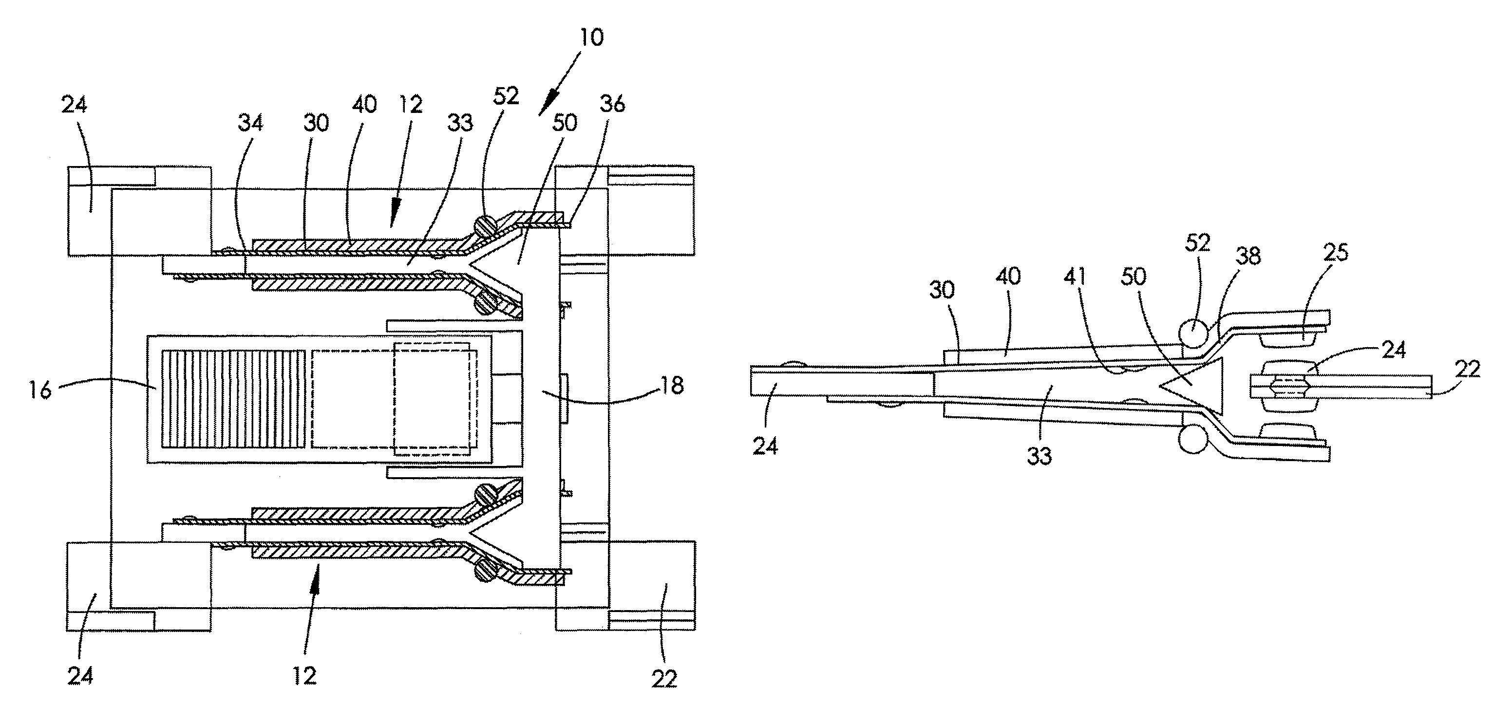
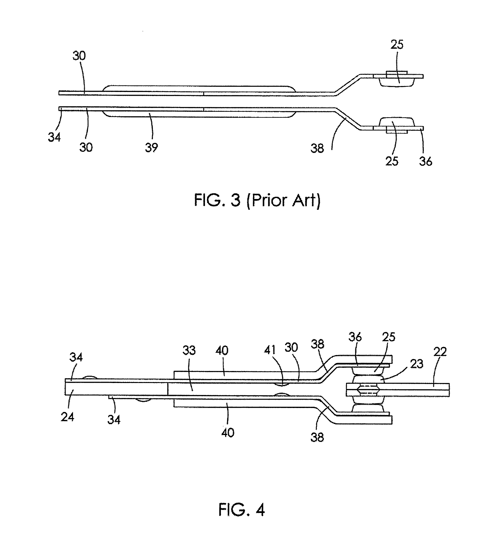
[0049]FIG. 4 is a schematic view of a pair of bi-blade movable arms 30 of an electrical contactor, according to a preferred embodiment of the present invention. Each arm is similar to the prior art arms of FIG. 3 except that the stiffing ribs 39 are replaced by ferrous plates, in the form of steel laminations 40, intimately attached to the outer surface of the arm. The steel lamination 40 extends over a majority of the length of the arm 30 and preferably extends over the sloped portion 38 and the distal end 36 of the arm. In FIG. 4, the fixed terminal 22 and ...


PUM


Abstract

A switching electrical power contactor having a bi-blade type switch, has ferrous plates attached to the blades to increase the current carrying capacity and reduce the resistance of the switch. Flexible tangs formed at the distal end of the blades cooperate with a movable member to hold the contacts closed when the contactor is in the closed state.

Description

CROSS REFERENCE TO RELATED APPLICATIONS[0001]This non-provisional patent application claims priority under 35 U.S.C. §119(a from Patent Application No. GB1200331.5 filed in United Kingdom on Jan. 9, 2012.FIELD OF THE INVENTION[0002]This invention relates to an electrical power switching contactor and in particular, to a single-pole or two-pole contactor capable of switching currents of more than 80 amps at mains voltage.[0003]This invention also relates to the types of high-current switching contactors employed in modern electricity meters, so-called “smart meters”, for performing a pre-payment or safety-disconnect function at normal domestic supply (mains) voltages, e.g. 100 V AC to 240 V AC. It has a particular application to electrical contactors having a bi-blade contact arrangement as described in US Patent U.S. Pat. No. 7,833,034.BACKGROUND OF THE INVENTION[0004]Many contactors of this type are capable of switching nominal current at say 100 Amps or 200 Amps, for a large numbe...

Claims


Application Information

Patent Timeline
Patent Type & Authority Patents(United States)
IPC IPC(8): H01R13/64G01R11/04H01H1/54H01H50/54H01H50/64H02B1/42
CPCG01R11/04H01H50/641H01H1/54H01R13/64H02B1/42H01H50/54H01H1/021H01H50/648H01H2205/002G01R11/02H01R13/18H01R33/00
Inventor CONNELL, RICHARD, ANTHONY
Owner JOHNSON ELECTRIC INT UK
Why Eureka
Try Eureka