Posterior prosthetic intervertebral disc

a technology of intervertebral discs and prosthetic discs, which is applied in the field of medical devices and methods, can solve the problems of back pain, degeneration and/or dysfunction of one or more intervertebral discs, and the health and productivity of people around the world, and achieve the effect of increasing the disc height and increasing the disc heigh

Active Publication Date: 2014-09-30
SIMPLIFY MEDICAL PTY LTD
View PDF419 Cites 11 Cited by
  • Summary
  • Abstract
  • Description
  • Claims
  • Application Information

AI Technical Summary

Benefits of technology

[0012]In accordance with one aspect of the invention, a prosthetic intervertebral disc includes first and second end plates sized and shaped to fit within an intervertebral space, each end plate having a vertebral contacting surface and an inner surface and a first bearing surface on an inner surface of the first end plate and a second bearing surface on an inner surface of the second end plate. The first and second bearing surfaces are arranged to allow articulation and rotation between the first and second plates. The first and second plates are each formed of first, second and third parts having a first configuration in which the parts are axially aligned to a second configuration in which the parts are axially unaligned with each other. The first and second plates are deployed in situ from the first configuration to the second configuration by both rotation and sliding of the parts over one another. The deployment from the first configuration to the second configuration increases a height of the disc.
[0013]In accordance with another embodiment of the invention, a prosthetic intervertebral disc includes first and second end plates sized and shaped to fit within an intervertebral space, each end plate having a vertebral contacting surface and an inner surface, a first bearing surface on an inner surface of the first end plate and a second bearing surface on an inner surface of the second end plate, the first and second bearing surfaces opposed to one another, and a mobile core configured to be received between the first and second bearing surfaces and arranged to allow articulation and rotation between the first and second plates. The first and second plates are each formed of first, second and third parts having a first configuration in which the parts are axially aligned and a second configuration in which the parts are axially unaligned with each other. A track is formed in the first and second end plates. The track is configured to allow the mobile core to move from a first position outside of the bearing surfaces to a position between the bearing surfaces, wherein the movement of the mobile core from the first position to the second position increases a height of the disc.
[0014]In accordance with a further aspect of the invention, a method of deploying a prosthetic intervertebral disc comprises the steps of: providing a prosthetic intervertebral disc having first and second end plates each having a vertebral contacting surface and an inner surface, a first bearing surface on an inner surface of the first end plate and a second bearing surface on an inner surface of the second end plate, the first and second bearing surfaces arranged to allow articulation and rotation between the first and second plates, wherein the first and second plates are each formed of first, second and third parts; inserting the intervertebral disc between two vertebrae in a configuration in which the first, second and third parts of each of the plates are axially aligned; and deploying the first and second plates in situ from the first configuration to a second configuration in which the parts are axially unaligned with each other by both rotation and sliding of the parts over one another, wherein the deployment from the first configuration to the second configuration increases a height of the disc. In accordance with an additional aspect of the invention, a method of deploying a prosthetic intervertebral disc includes the steps of: providing a prosthetic intervertebral disc comprising first and second end plates and a mobile core arranged to allow articulation and rotation between the first and second plates, wherein the first and second plates are each formed of first, second and third parts; inserting the intervertebral disc between two vertebrae in a configuration in which the first, second and third parts of each of the plates are substantially axially aligned; deploying the first and second plates in situ from the first configuration to a second configuration in which the parts are axially unaligned with each other; and moving the mobile core along a track between the end plates, wherein the movement of the mobile core from the first position to the second position increases a height of the disc.

Problems solved by technology

Back pain takes an enormous toll on the health and productivity of people around the world.
One common cause of back pain is injury, degeneration and / or dysfunction of one or more intervertebral discs.
Discs often become damaged due to wear and tear or acute injury.
Degeneration or other damage to a disc may cause a loss of “disc height,” meaning that the natural space between two vertebrae decreases.
Decreased disc height may cause a disc to bulge, facet loads to increase, two vertebrae to rub together in an unnatural way and / or increased pressure on certain parts of the vertebrae and / or nerve roots, thus causing pain.
In general, chronic and acute damage to intervertebral discs is a common source of back related pain and loss of mobility.
When one or more damaged intervertebral disc cause a patient pain and discomfort, surgery is often required.
A potential drawback of these known disc designs is that the prosthetic disc must be inserted from the anterior side of the patient.
The anterior approach can be difficult and may require a vascular surgeon as the prosthetic disc passes near important blood vessels located anterior to the spine.
Other currently available intervertebral disc prostheses usually have similar drawbacks, including invasiveness of the surgery and / or surgical skill and complexity.
It is this limitation on space that has until now prevented the design of a successful artificial disc for delivery by a TLIF or PLIF approach.

Method used


Image

  • Posterior prosthetic intervertebral disc
  • Posterior prosthetic intervertebral disc
  • Posterior prosthetic intervertebral disc

Examples


Embodiment Construction

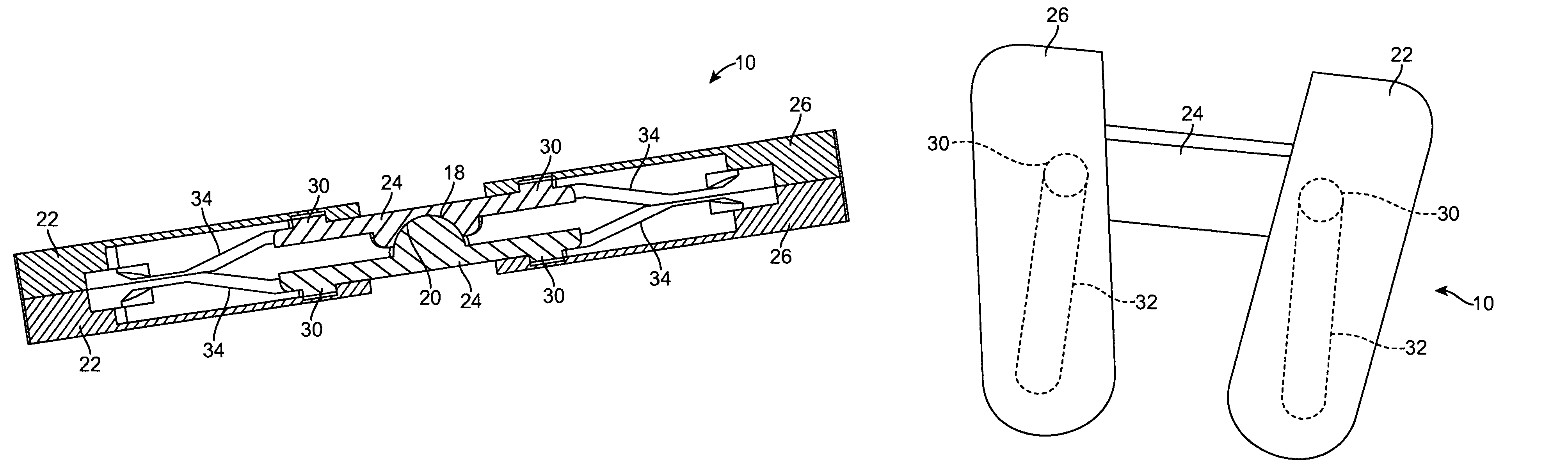
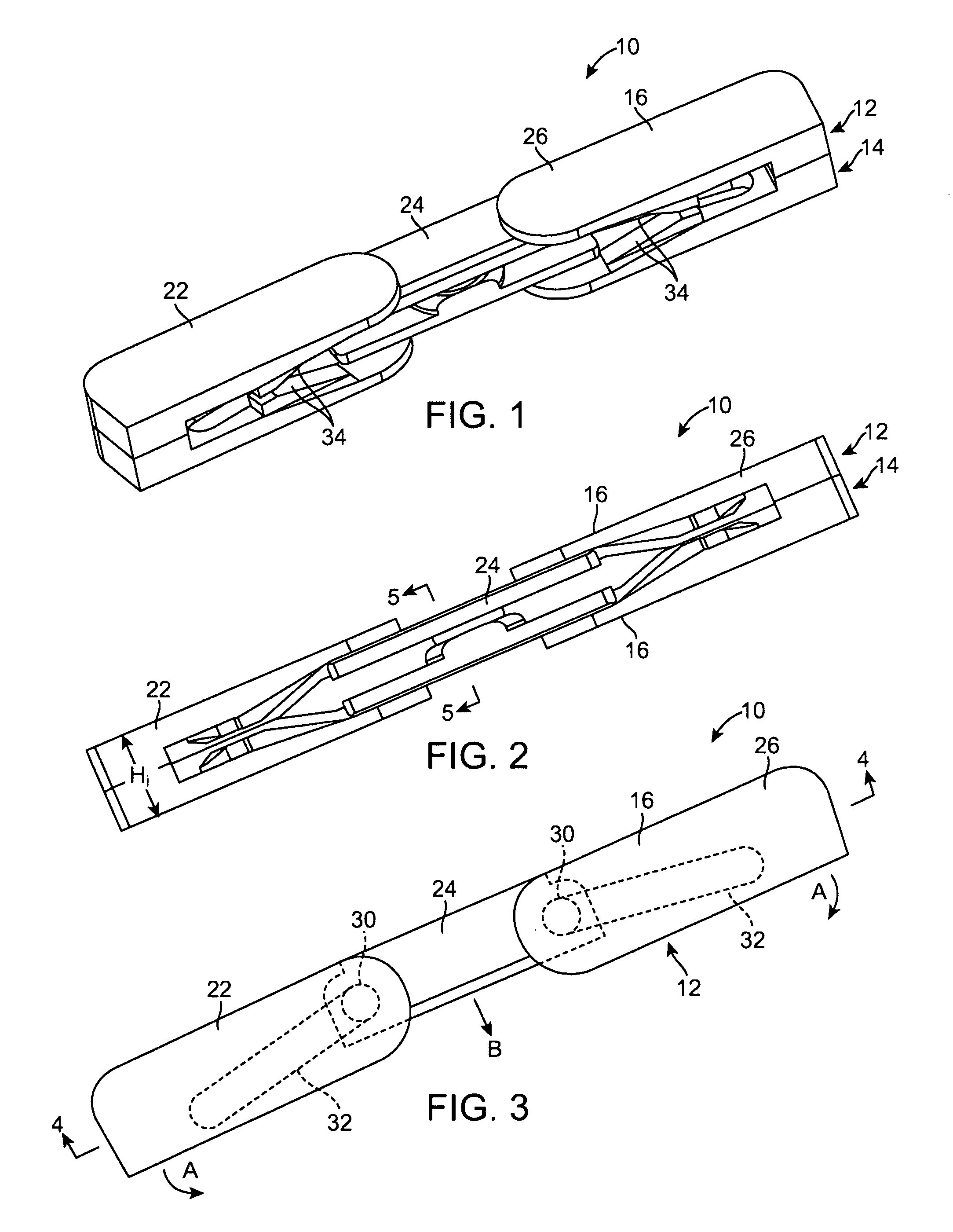
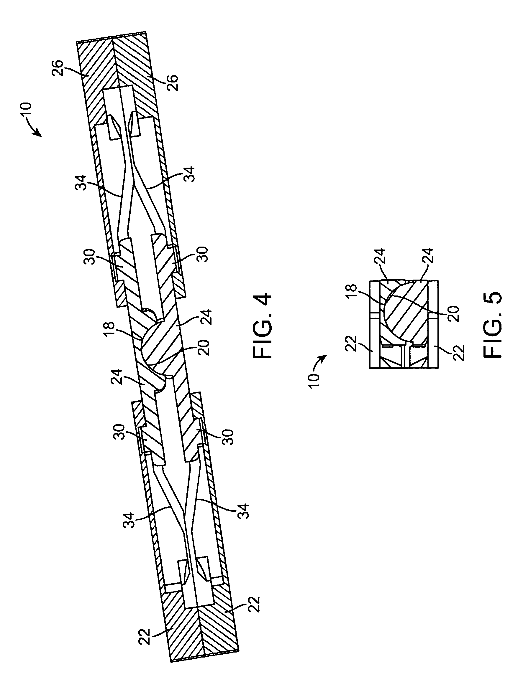
[0027]The present invention provides an implanted intervertebral disc assembly which both restores motion and can be implanted from the back of the patient, thereby decreasing the invasiveness of the procedure. The posterior approach provides for a smaller posterior surgical incision and avoids important blood vessels located anterior to the spine particularly for lumbar disc replacements. The intervertebral discs described herein are designed to be suitable for either a PLIF or TLIF approach to the spine. These approaches require insertion of a device with a small insertion profile which can be expanded or assembled in vivo into a complete disc assembly.

[0028]PLIF stands for Posterior Lumbar Interbody Fusion. In the PLIF approach to the spine, the vertebrae are reached through an incision in the patient's back (posterior). The PLIF procedure involves forming a 3-6 inch incision in the patient's back and retracting the spinal muscles to allow access to the vertebral disc. The surgeo...


PUM

PropertyMeasurementUnit
widthaaaaaaaaaa
heightaaaaaaaaaa
widthaaaaaaaaaa

Abstract

A prosthetic intervertebral disc is formed of first and second end plates sized and shaped to fit within an intervertebral space and to be implanted from the back of the patient, thereby decreasing the invasiveness of the procedure. The posterior approach provides for a smaller posterior surgical incision and avoids important blood vessels located anterior to the spine particularly for lumbar disc replacements. The first and second plates are each formed of first, second and third parts are arranged in a first configuration in which the parts are axially aligned to form a low profile device appropriate for insertion through the small opening available in the TLIF or PLIF approaches described above. The three parts of both of the plates rotate and translate with respect to one another in situ to a second configuration or a deployed configuration in which the parts are axially unaligned with each other to provide a maximum coverage of the vertebral end plates for a minimum of insertion profile. Upon deployment of the disc, a height of the disc is increased.

Description

CROSS-REFERENCES TO RELATED APPLICATIONS[0001]This application claims priority to U.S. Provisional Application No. 61 / 081,952 filed Jul. 18, 2008, entitled “POSTERIOR PROSTHETIC INTERVERTEBRAL DISC” the full disclosure of which is incorporated herein by reference.BACKGROUND OF THE INVENTION[0002]The present invention relates to medical devices and methods. More specifically, the invention relates to intervertebral prosthetic discs and methods of preserving limited motion upon removal of an intervertebral disc.[0003]Back pain takes an enormous toll on the health and productivity of people around the world. According to the American Academy of Orthopedic Surgeons, approximately 80 percent of Americans will experience back pain at some time in their life. In the year 2000, approximately 26 million visits were made to physicians' offices due to back problems in the United States. On any one day, it is estimated that 5% of the working population in America is disabled by back pain.[0004]...

Claims


Application Information

Patent Timeline
Patent Type & Authority Patents(United States)
IPC IPC(8): A61F2/44A61F2/30
CPCA61F2/4425A61F2310/0088A61F2250/0009A61F2/30965A61F2002/30166A61F2250/0098A61F2002/30663A61F2002/30471A61F2310/00017A61F2002/3008A61F2230/0028A61F2002/30904A61F2220/0033A61F2220/0091A61F2002/30579A61F2002/30556A61F2310/00029A61F2310/00407A61F2002/443A61F2310/00796A61F2002/30662A61F2002/30649A61F2002/30841A61F2310/00023A61F2002/30364A61F2002/4415A61F2220/0016A61F2/442A61F2/4611
Inventor DE VILLIERS, MALANJANSEN, NEVILLE
Owner SIMPLIFY MEDICAL PTY LTD
Why Eureka
Try Eureka