Pulse phase difference coding circuit

a coding circuit and phase difference technology, applied in the field of pulse phase difference coding circuits, can solve the problems of increasing the size power consumption, non-uniform delays in individual delay elements, and so as to reduce the performance of the pulse phase difference coding circuit. the effect of reducing the number of delay elements

Inactive Publication Date: 2014-09-30
DENSO CORP
View PDF9 Cites 0 Cited by
  • Summary
  • Abstract
  • Description
  • Claims
  • Application Information

AI Technical Summary

Benefits of technology

[0016]An embodiment provides a pulse phase difference coding circuit which reduces the number of delay elements configuring a pulse delay circuit without lowering the performance of the pulse phase difference coding circuit.

Problems solved by technology

The rate of operation of the synchronous counter is limited by the delay time of a carry line.
However, as the number of delay elements is increased, the size of a circuit detecting the position of a circulating pulse signal and the size of a circuit coding the detected position of the circulating pulse signal into numeric data increase, which increases the size of the pulse phase difference coding circuit and power consumption.
This is because the delay is increased where the delay elements straddle the logical block compared with where the delay elements are placed in the same logical block, which makes the delays in the individual delay elements nonuniform, thereby lowering accuracy of measurement.
As described above, when the number of the delay elements configuring the pulse delay circuit cannot be increased for some reason, the number of digits of the counter circuit is limited.
Hence, the performance of the pulse phase difference coding circuit cannot be improved, which considerably limits the use for the pulse phase difference coding circuit.

Method used


Image

  • Pulse phase difference coding circuit
  • Pulse phase difference coding circuit
  • Pulse phase difference coding circuit

Examples


Embodiment Construction

[0022]With reference to the accompanying drawings, hereinafter are described embodiments. Throughout the drawings, components identical with or similar to each other are given the same numerals for the sake of omitting unnecessary explanation.

[0023](Entire Configuration)

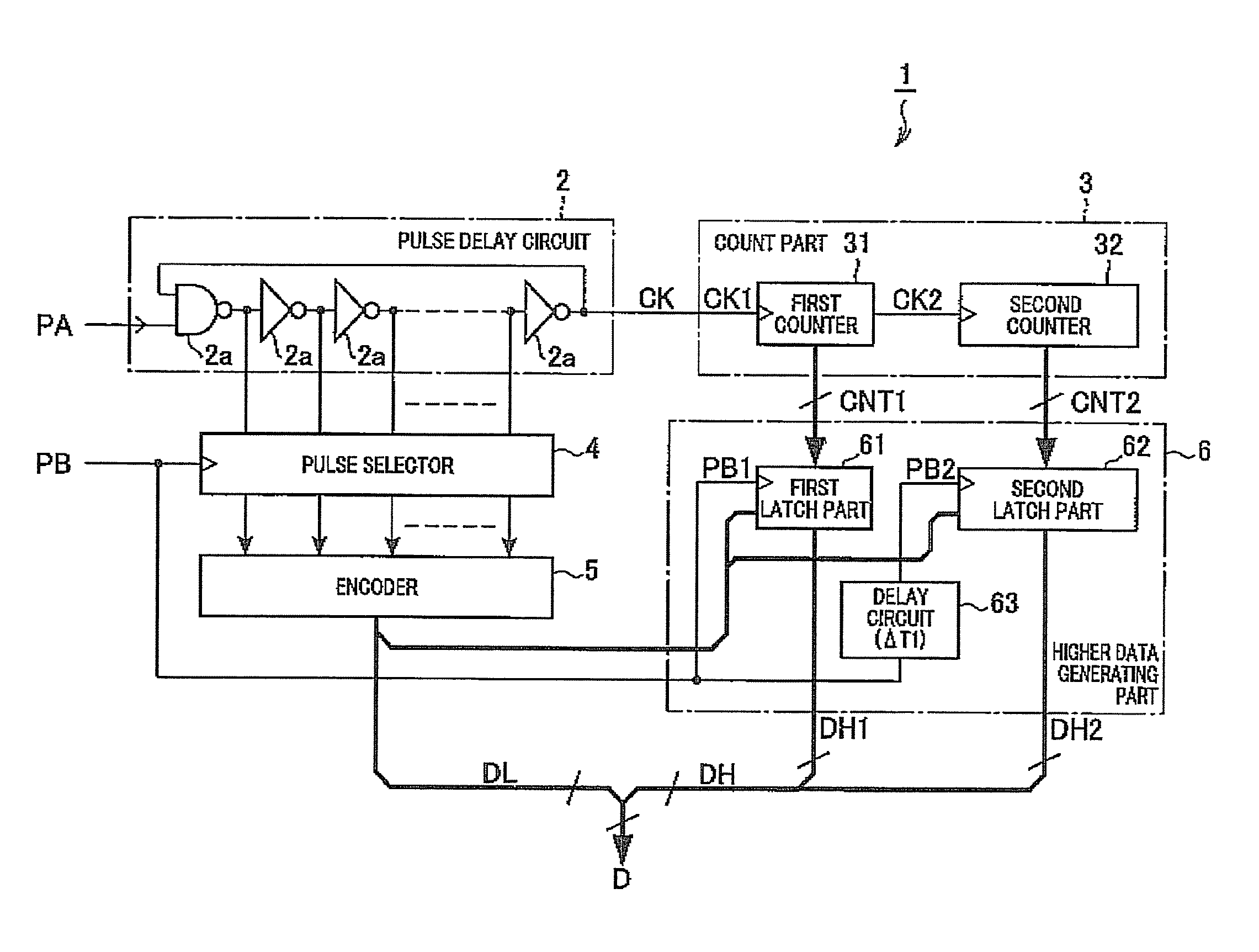
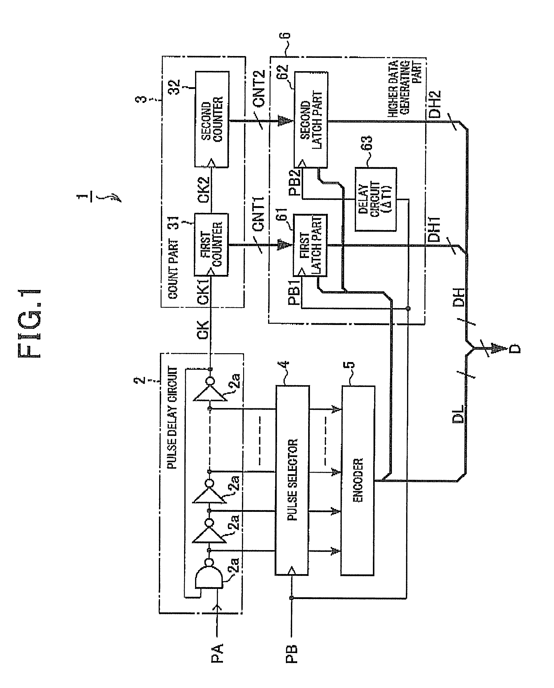
[0024]FIG. 1 is a block diagram showing an entire configuration of a pulse phase difference coding circuit 1 which codes a phase difference between a pulse for activation PA (activation pulse PA) and a pulse for measurement PB (measurement pulse PB) into numeric data.

[0025]As shown in FIG. 1, the pulse phase difference coding circuit 1 is configured with a ring delay line (RDL) formed by connecting a plurality of delay elements 2a in a ring shape. The pulse phase difference coding circuit 1 includes a pulse delay circuit 2 and a count part 3. When the pulse for activation PA is inputted into the pulse delay circuit 2 from an external unit, the pulse delay circuit 2 transmits pulse signals in sequence with delay. The ...


PUM


Abstract

In a pulse phase difference coding circuit, a count unit includes a plurality of partial counters connected to each other in series so that the most significant bit of an output of the previous stage serves as an operation clock of the subsequent stage. A circulation number detecting unit includes a first latch circuit which is provided for each of the partial counters and latches an output of the partial counter according to a pulse for measurement, and a first delay circuit which treats the partial counter in the second stage or later as an object counter and delays the pulse for measurement by a total delay time in all the partial counters located at the previous stages of the object counter. The pulse for measurement is inputted into the first latch circuit which latches an output of the object counter.

Description

CROSS-REFERENCE TO RELATED APPLICATION[0001]This application is based on and claims the benefit of priority from earlier Japanese Patent Application No. 2010-272594 filed Dec. 7, 2010, the description of which is incorporated herein by reference.BACKGROUND[0002]1. Technical Field[0003]The present invention relates to a pulse phase difference coding circuit which uses a pulse delay circuit formed by connecting a plurality of delay elements in a ring shape to code the phase difference of a pulse signal.[0004]2. Related Art[0005]Conventionally, pulse phase difference coding circuits are known. In a pulse phase difference coding circuit (which is disclosed in, for example, JP-A-6-283984), a pulse delay circuit is used which is formed by connecting a plurality of delay elements in a ring shape. When a pulse for activation is inputted, the pulse delay circuit is activated. When a pulse for measurement is inputted, the position of a pulse signal circulating in the pulse delay circuit and t...

Claims


Application Information

Patent Timeline
Patent Type & Authority Patents(United States)
IPC IPC(8): H03M1/60G08C19/12
CPCG08C19/12
Inventor YAMAUCHI, SHIGENORI
Owner DENSO CORP
Why Eureka
Try Eureka