Processing method using an electric tool

a technology of electric tools and workpieces, applied in the field of workpiece processing methods, can solve the problems of time-consuming measurement of working area and/or workpieces, inaccurate processing, and inability to accurately process, etc., to achieve easy and cost-effective work, facilitate work on a plane which occurs frequently, and facilitate calibration.

Inactive Publication Date: 2014-09-30
MARQUARDT GMBH SCHLOSSTRASSE 16 7201 RIETHEIM-WEILHEIM 1 WEST GERMANY
View PDF12 Cites 2 Cited by
  • Summary
  • Abstract
  • Description
  • Claims
  • Application Information

AI Technical Summary

Benefits of technology

[0005]The invention is based on the object of further developing the manually controlled method for processing of workpieces by means of a movable appliance, such that the work of the electric tool user is made easier and these tools are made more useful to the user. One particular aim is to specify a method for processing of workpieces by means of a movable appliance, which achieves high accuracy and, in particular, is as labor saving as possible, with minimal hardware complexity. A further aim is to provide an apparatus which is suitable for this purpose.
[0006]In the method according to the invention, essentially continuous position identification, in particular by means of optical methods, is carried out for the respective actual position of the appliance and / or of an object which can be moved corresponding to the appliance. The position information determined in this way, such as the coordinates of the respective determined actual position and / or information relating to any discrepancy between the nominal position and the actual position, is then indicated to the user on the appliance, for manual position control. A navigation method is therefore provided for working with electric tools on a plane and / or in space. This method advantageously allows quick and simple work on the plane and / or in space, for example when drilling holes which are positioned relative to one another.
[0007]In another embodiment of the method according to the invention, the respective position information is transmitted wirelessly to the appliance, thus allowing the appliance to be handled by the user without any restrictions.
[0012]In another embodiment, which can be implemented easily and is cost-effective, two-dimensional (2D) navigation is carried out on the basis of the “laser mouse” principle, as known from computer technology. For this purpose, a sensor which is located on the appliance detects the changes in the structure on the workpiece during movement of the appliance. The relative movement of the appliance can be determined from the detected changes in the structure. The distance traveled by the power tool and / or the integrated speeds of the power tool, which are determined on the basis of the relative movement, in turn make it possible to determine the position information for the appliance.
[0018]The advantages achieved by the invention are, in particular, that the work on a plane which occurs frequently is made easier by means of the appliance. In particular, grid-like tasks can be carried out easily and cost-effectively with the aid of the method according to the invention and / or the apparatus according to the invention. The proposed method requires relatively uncomplex hardware. The calibration can be carried out quickly and easily. Before work starts, all that is necessary is to place the calibration cross on the working plane in order to allow the camera and the image evaluation computer to carry out the calibration. Relative coordinates, which can be indicated on the appliance, are available to the user. In consequence, the user need not do any calculations to find the desired positions, but he can in fact transfer the dimensions from a dimensioned plan, in a simple manner.

Problems solved by technology

It is immediately evident that the processing accuracy can suffer from this.
When a plurality of successive nominal positions are intended to be achieved, for example, in order to produce a hole pattern, then this process is not only inaccurate but is also tedious.
In particular, in this case, time-consuming measurements of the working area and / or of the workpiece are necessary.

Method used


Image

  • Processing method using an electric tool
  • Processing method using an electric tool
  • Processing method using an electric tool

Examples


Embodiment Construction

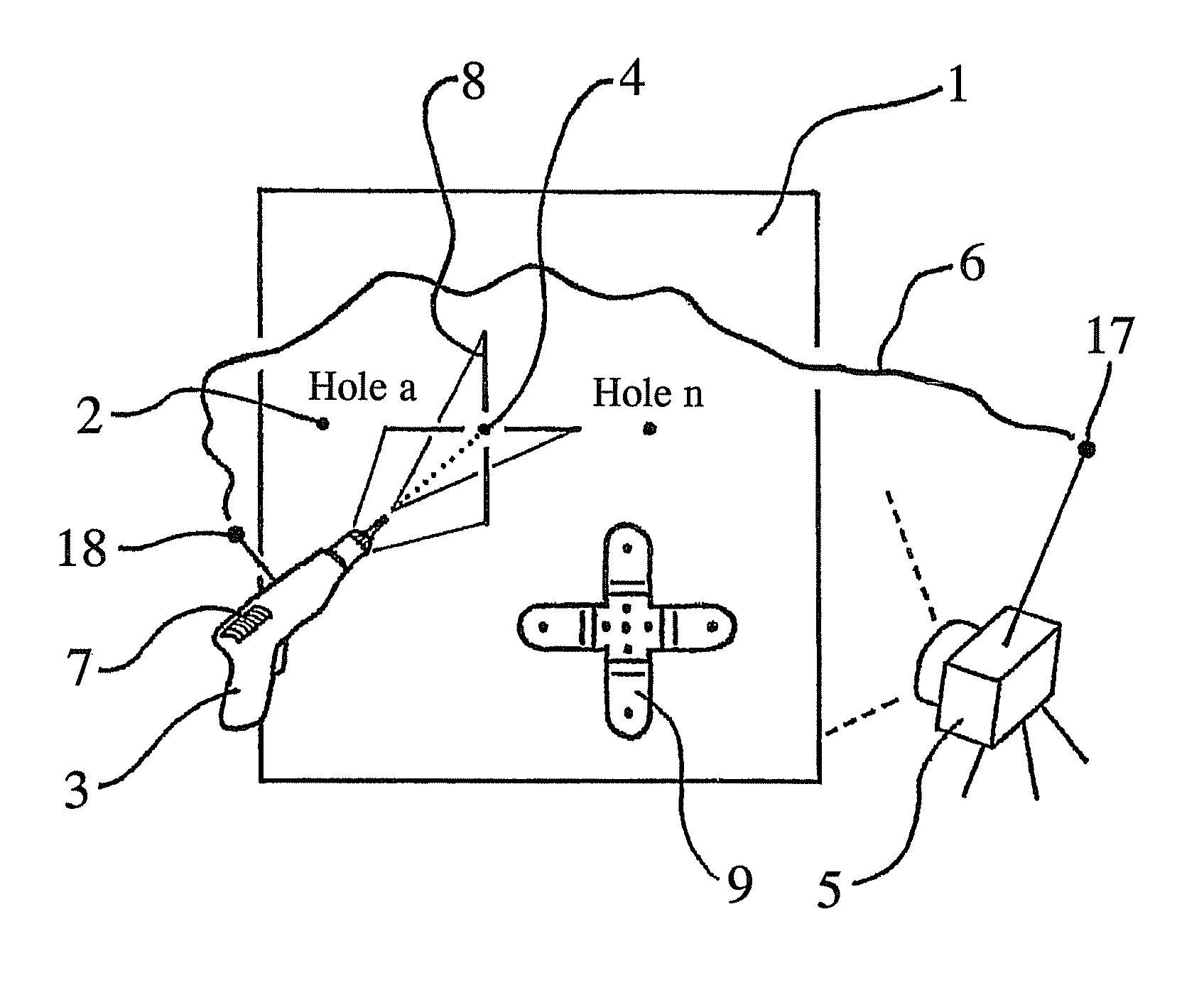
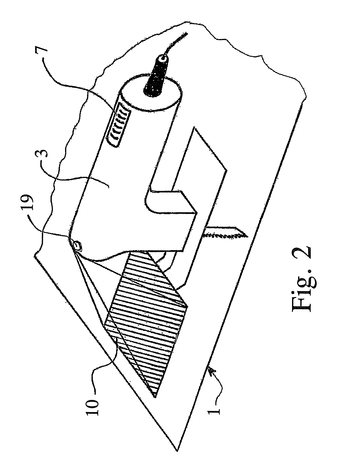
[0025]The method for processing a workpiece 1 will be explained in more detail with reference to FIG. 1. The workpiece 1 may be a wall, a ceiling, a floor or the like in a building, wherein, for example, the intention is to introduce a hole into the workpiece 1 at least one nominal position 2 by means of a movable appliance 3 which is controlled by hand. The appliance 3 is an electric tool, for example a drilling machine, an impact drilling machine or a hammer drill. In order to allow the appliance 3 to be moved to the predeterminable nominal position, essentially continuous position identification is carried out for the respective actual position of the appliance 3. An object 4 which can be moved corresponding to the appliance 3 is detected for this purpose, in which case the object 4 is a light spot projected by the appliance 3 onto the workpiece 1. Detection is carried out by optical methods, to be precise in this case by recording by means of a camera 5, and the detection proces...


PUM


Abstract

The invention relates to a method and an apparatus for processing a workpiece, such as a wall, a ceiling, a floor or the like in a building, by means of an appliance which can be moved, in particular an electric tool, wherein the appliance can be moved to at least one predeterminable nominal position. Essentially continuous position identification, in particular by means of optical methods, is carried out for the respective actual position of the appliance and / or of an object which can be moved corresponding to the appliance. The position information, such as the coordinates of the respective determined actual position and / or information relating to any, discrepancy between the nominal position and the actual position, is transmitted wirelessly to the appliance. The respective position information is indicated to the user on the appliance, for manual position control.

Description

CROSS REFERENCE TO RELATED APPLICATIONS[0001]This application is a continuation of International Application No. PCT / DE2009 / 000396 filed Mar. 27, 2009, which designated the United States, and claims the benefit under 35 USC §119(a)-(d) of German Application No. 10 2008 016 021.0 filed Mar. 28, 2008, the entireties of which are incorporated herein by reference.FIELD OF THE INVENTION[0002]The invention relates to a method for processing a workpiece, and to a corresponding apparatus.BACKGROUND OF THE INVENTION[0003]Hand held electric tools, also referred to as power tools, are already used extensively for the processing of workpieces in buildings. The workpiece may be a wall, a ceiling, a floor or the like in the building.[0004]Workpieces such as these in buildings are frequently processed by means of a movable appliance, which is controlled by hand. In this case, the user moves the appliance by hand to a predetermined nominal position. It is immediately evident that the processing acc...

Claims


Application Information

Patent Timeline
Patent Type & Authority Patents(United States)
IPC IPC(8): H04N7/18G06K9/36B25H1/00
CPCB25H1/0085G01S5/163G01S11/02
Inventor FUCHS, ANDREASGANZ, JOCHEN
Owner MARQUARDT GMBH SCHLOSSTRASSE 16 7201 RIETHEIM-WEILHEIM 1 WEST GERMANY
Why Eureka
Try Eureka