Heated insole remote control systems

a remote control system and heated insole technology, applied in the field of remote control of heated insoles, can solve the problems of increasing risk or injury, affecting the effect of the temperature of the insole, and consuming time in the process, so as to improve the ability to achieve desired temperatures and keep the rest of the body warm

Active Publication Date: 2014-10-07
SCHAWBEL TECH
View PDF11 Cites 16 Cited by
  • Summary
  • Abstract
  • Description
  • Claims
  • Application Information

AI Technical Summary

Benefits of technology

[0003]The present invention is directed to heating insoles of footwear, and improving the ability to realize desired temperatures through wireless control signals. Heated insoles are intended to aid a user in withstanding cold weather by providing supplementary heat in the case where normal body heating is not enough or when additional heat is desired to be more comfortable. When an extremity of the body starts to become cold, the body's natural physiological response of vasoconstriction occurs in which the nervous system restricts blood flow to the cold extremity in an effort to keep the rest of the body warm. It is well known that frostbite and other cold related injuries occur first in fingers and toes due to vasoconstriction and keeping these extremities warm will help insure survival or at minimum a more pleasurable outdoor experience.
[0004]Heated insoles are a key component to preventing injury in cold weather and are well known to hunters and outdoorsmen as standard survival gear while in the woods or forest. A problem exists however in the control of such insoles as often the insole temperature needs to be adjusted to accommodate different conditions and comfort levels. Standard temperature adjustment methods require the user needs to remove his or her boot to gain access to the insole in order to make desired adjustments. Not only is this procedure time consuming but removing the user's foot from the boot to gain access to the insole exposes the foot to the cold conditions. This adjustment procedure undoubtedly lowers the foot temperature even further thereby further increasing risk or injury.
[0007]Additionally, the location of the RF receiver, inside shoes, adjacent to the ground requires special consideration to overcome signal loss. Prior art radio controlled insoles include the wire antenna along the midline of the insole. This has been problematic because signal strength is affected. The inventors realized that much of the transmitted signal is blocked by the ground from reaching the receiver antenna located in the insole. The foot and body of the wearer also tend to block the signal. One improvement of this invention for the receiver antenna is to locate it more advantageously for signal reception, for instance, near the outer margin of the insole. Reception is materially improved with such an antenna.
[0010]The present invention also discloses a system and method of communication that helps to ensure that user commands are more effectively transmitted by providing a plurality of transmissions at specific spaced intervals of time. By providing discrete, timed transmissions after the user temperature control has been initiated, the probability of transmissions coinciding with the user taking a step and lifting his foot off the ground is increased. The timed control signal may be initiated by the remote or may be controlled by a microprocessor within the insole. With the foot off the ground, the distance between the horizontally placed antenna within the insole and the earth's surface is greatly increased, thus increasing the reception range for the insole. A secondary action that occurs while a foot is in the air is that the pressure of the person wearing the shoe is relieved from the insole, decompressing the foam some measurable amount between the antenna and the person. This decompression although small, tends to increase the transmission success thus providing a better user experience.
[0013]Knowing that each foot is off the ground once per second for almost a second, allows more robust communication by providing transmissions that occur while the foot position is in the air and not on the ground surface. Transmissions every half second will insure some of the broadcasted signal will be simultaneous with the foot being in the air, thus delivering the intended command to the insole device. Other time periods may be chosen in accordance with prevailing governmental regulation.
[0015]Transmitting the sequence of coded signals periodically for a short period of time after the initiation of the process to heat the insole increases the ability of the user to more effectively communicate the heating instructions to the insole.

Problems solved by technology

A problem exists however in the control of such insoles as often the insole temperature needs to be adjusted to accommodate different conditions and comfort levels.
Not only is this procedure time consuming but removing the user's foot from the boot to gain access to the insole exposes the foot to the cold conditions.
This adjustment procedure undoubtedly lowers the foot temperature even further thereby further increasing risk or injury.
Although this improved method of control is an improvement, the design requirements for a proper fitting heated insole yields conditions not optimum for wireless control as will be pointed out in the following discussion.
A problem exists in the prior art however in which this restrictive antenna positioning tends to prohibit the reception of information transmitted from the hand held unit to the receiver unit due to the signal grounding effect produced by the earth's surface on the bottom and the user's foot on top of the antenna.
This grounding effect is often severe enough that it inhibits information from the transmitter to the receiver unit, therefore preventing any heating adjustments to be made.

Method used


Image

  • Heated insole remote control systems
  • Heated insole remote control systems
  • Heated insole remote control systems

Examples


Embodiment Construction

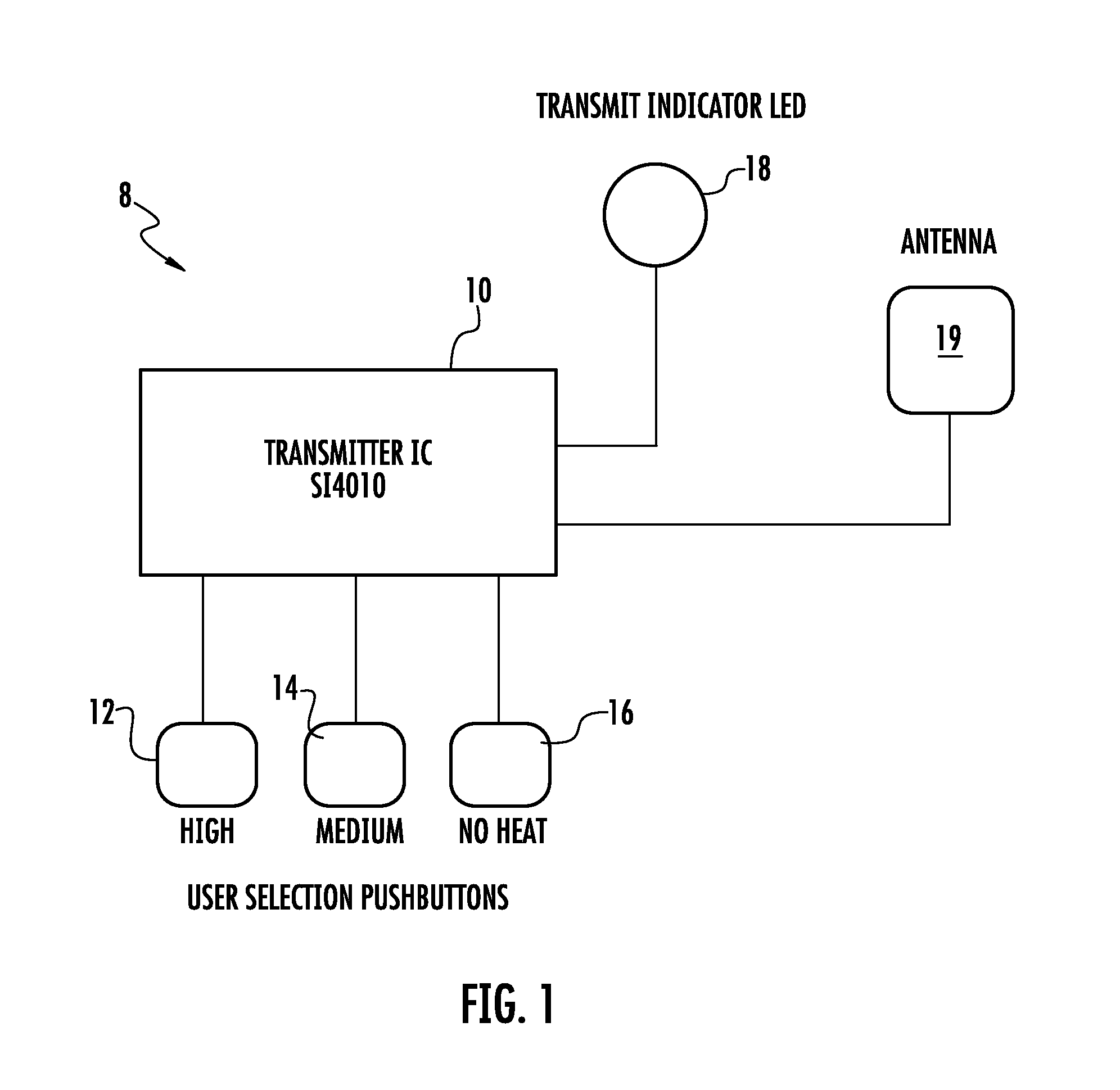
[0022]FIG. 1 is a block diagram showing the transmitter 10 of this invention. The transmitter comprises an integrated circuit S14010 which is connected to a plurality of push buttons 12, 14 and 16. The push buttons generate signals to cause high, medium and no heat conditions, respectively, to be generated within the insole. The user selects a push button to be activated in order to control the temperature within the insole.

[0023]An LED 18 may be connected to the transmitter to indicate that the transmitter is transmitting and / or to indicate that the transmitter is on and capable of transmitting. An antenna 19 connected to the transmitter wirelessly transmits electronic signals generated in transmitter 10 to the electrical circuit within the insole.

[0024]The transmitter 10 decodes the user command by determining which of the push buttons is selected, and the transmitter provides a burst of four packets of information or electrical signals with each packet consisting of an address an...


PUM


Abstract

A remote control wireless heated insole system in which address data identifying specific insoles to be heated is provided. Once the heating process is initiated, periodic repeated control signals are generated to cause heating of the insoles.

Description

RELATED APPLICATIONS[0001]This application is based on Provisional Patent Application Ser. No. 61 / 427,509, filed Dec. 28, 2010, the contents of which are incorporated herewith and the priority of which is claimed.BACKGROUND OF THE INVENTIONField of the Invention[0002]The present invention relates to a remotely controlled heated insole for footwear and to an improved method of control of such heated insoles that provides a more reliable means of ensuring that the temperature desired by the user is realized.BRIEF DESCRIPTION OF THE INVENTION[0003]The present invention is directed to heating insoles of footwear, and improving the ability to realize desired temperatures through wireless control signals. Heated insoles are intended to aid a user in withstanding cold weather by providing supplementary heat in the case where normal body heating is not enough or when additional heat is desired to be more comfortable. When an extremity of the body starts to become cold, the body's natural ph...

Claims


Application Information

Patent Timeline
Patent Type & Authority Patents(United States)
IPC IPC(8): A43B7/02A43B3/35
CPCA43B3/0015A43B7/02A43B7/04H05B3/02A43B13/38A43B3/38A43B3/35G05B15/02G05D23/1917G08C17/02
Inventor WHITEHEAD, IANLYNCH, JAMES K.
Owner SCHAWBEL TECH
Why Eureka
Try Eureka