Gas carrying threading device of sewing machine

a threading device and sewing machine technology, applied in sewing apparatus, thin material handling, textiles and papermaking, etc., can solve the problems of difficulty in understanding the use of the threading device for the operator, and the operation of the looper thread which is performed by both hands concurrently, so as to prevent the completion of threading and facilitate the operation. , the effect of easy operation

Active Publication Date: 2014-10-14
SUZUKI MFG CO LTD
View PDF19 Cites 9 Cited by
  • Summary
  • Abstract
  • Description
  • Claims
  • Application Information

AI Technical Summary

Benefits of technology

[0024]According to the gas carrying threading device of sewing machine of the present invention, the looper threading can be performed by one-handed three operations which are a threading preparatory operation, a threading positioning / connecting pulley operation and a threading gas supply operation.
[0025]Therefore, according to the gas carrying threading device of sewing machine of the present invention, by connecting with the hollow thread guide portion which leads to the thread introduction portion which inserts the thread from the thread outlet of the loop-taker point of the looper, the complicated thread guard is unnecessary and the threading that the handleability is easy can be performed. And, there are no mistake of the threading, no protrusion of the looper thread in mid-process, and no entanglement of the inserted looper thread with other thread. Besides, because the looper thread is fed by utilizing the flow of the pressurized gas which is supplied to the hollow thread guide portion, the threading can be performed at once by the extremely easy operation.
[0026]Besides, according to the gas carrying threading device of sewing machine of the present invention, because the safety device works depending on a movement position of the connecting movement plate and the power source to a sewing machine motor is disconnected, a breakage of the serger by such as incorrect operation to a motor controller during the threading preparatory operation and a completion of the threading can be prevented.

Problems solved by technology

Therefore, it is difficult to understand how to use this threading device for the operator who is not familiar with the sewing machine, and an insertion operation of the looper thread which is performed by using both hands concurrently is considerably complex, thereby the training of that purpose is necessary.

Method used


Image

  • Gas carrying threading device of sewing machine
  • Gas carrying threading device of sewing machine
  • Gas carrying threading device of sewing machine

Examples


Embodiment Construction

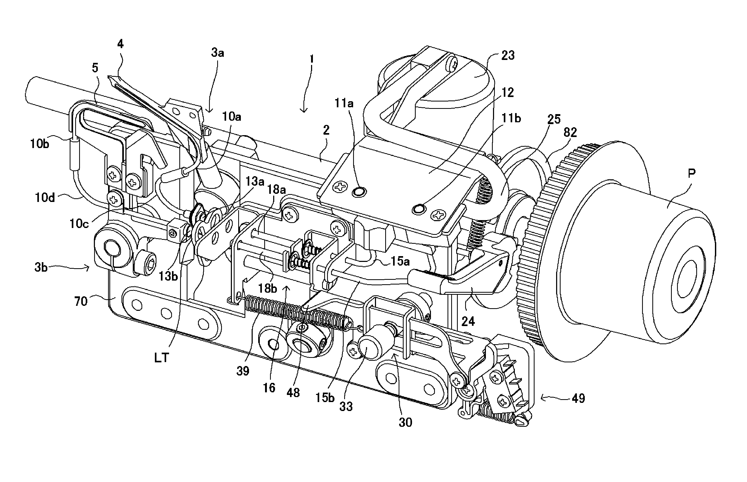
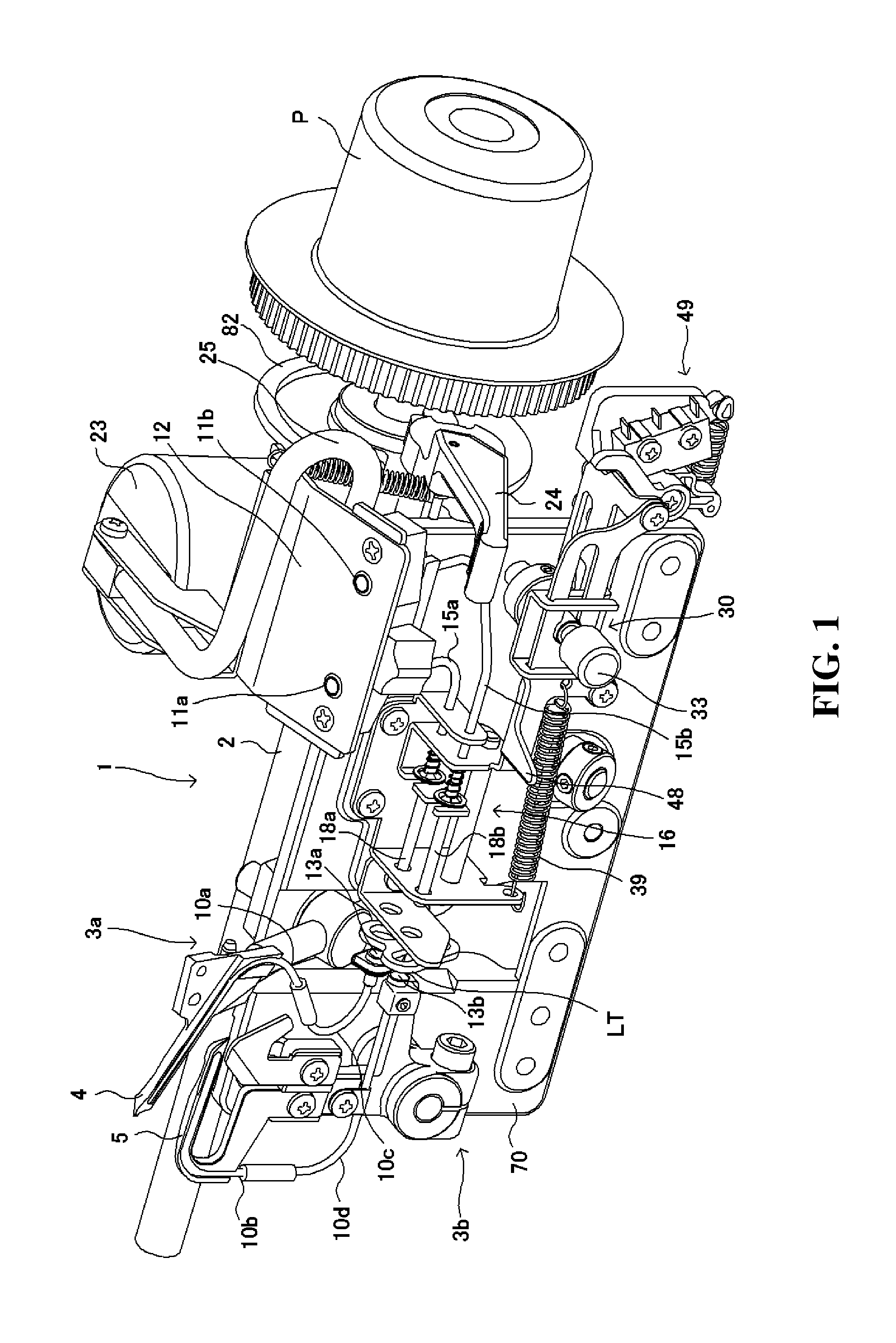
[0037]Hereinafter, the preferable embodiment that the gas carrying threading device of sewing machine of the present invention is applied to the serger is explained in detail by referring to the drawings.

[0038]As shown in FIG. 1 and FIG. 9, the serger 1 is composed from a main frame and a sub-frame which form a bed and an arm.

[0039]The sewing machine motor M is attached to the sub-frame, and a main shaft 2 lengthens along the frame in a horizontal direction. The main shaft 2 is rotated and driven by using a timing belt MB by the sewing machine motor M.

[0040]The stitch forming device is composed by the upper looper 4 and lower looper 5 which are driven by the looper drive mechanism 3 (3a, 3b) by synchronizing to the main shaft 2, the needle which is driven by the needle drive mechanism 6, a presser foot mechanism which presses a cloth on a throat plate and a cloth feed mechanism 7 which forwards the cloth every one stitch. In addition, because the concrete structure and the motion ar...


PUM


Abstract

A threading to a looper is performed with one-touch operation. A looper threading / sewing changeover mechanism 30 including a push button 33 for a pressing operation of a push button shaft 32 that a control pin 31 is protruded and provided, a control groove cam 38 which includes a first control groove cam portion 34—a fourth control groove cam portion 37 which receive the control pin, a connecting movement plate 40 which supports a thread guide portion and which is elastically repelled toward a threading state that a thread guide outlet of the thread guide portion contacts to a looper thread inlet of the looper by a first spring 39, and a connecting positioning plate 82 which rotates together with a main shaft 2 integrally and has a peripheral surface 80 that a tip portion 41 of the push button shaft contacts and has a notch portion 81 that the tip portion of the push button shaft is fitted is provided.

Description

FIELD OF THE ART[0001]The present invention relates to a gas carrying threading device of sewing machine, particularly relates to the gas carrying threading device of sewing machine such as a serger, a double chain stitch sewing machine, or a cover stitch sewing machine for performing a threading of a looper thread automatically to a looper by utilizing a pressurized gas.BACKGROUND OF THE ART[0002]Conventionally, in the serger, the double chain stitch sewing machine, or the cover stitch sewing machine, etc., the gas carrying threading device which is connected by a hollow looper thread guide which leads to a looper thread guide outlet of a loop-taker point of the looper from a thread introduction portion which inserts the looper thread and which feeds a looper thread by utilizing a flow of a pressurized gas which is supplied to the hollow looper thread guide is known. Hereby, a complicated thread guard is unnecessary and a threading that a handleability is easy can be performed. The...

Claims


Application Information

Patent Timeline
Patent Type & Authority Patents(United States)
IPC IPC(8): D05B57/02D05B57/34D05B63/02D05B87/00
CPCD05B57/34D05B63/02D05B87/00D05D2207/04D05B87/02D05B63/00D05B57/02
Inventor SAKUMA, KOUICHIISHIKAWA, MASATOSATOU, MITSURU
Owner SUZUKI MFG CO LTD
Why Eureka
Try Eureka