Spray gun with pressure measuring device

a technology of pressure measurement device and spray gun, which is applied in the direction of spray nozzles, instruments, packaging, etc., can solve the problems of cumbersome battery replacement, unintended adjustment, and user difficulty in reading the pressure display

Active Publication Date: 2014-10-14
SATA GMBH & CO KG
View PDF31 Cites 27 Cited by
  • Summary
  • Abstract
  • Description
  • Claims
  • Application Information

AI Technical Summary

Benefits of technology

[0006]With the spray gun, in accordance with the invention, it is possible for the pressure measuring device not to be soiled or damaged during cleaning operations and for a battery replacement during the use of a digital manometer to be carried out simply. With the spray gun, in accordance with the invention, it is ensured that the pressure display of the pressure measuring device is stationary, independent of the setting of regulation of the supply of compressed air, and that it can be read well at any time and that an unintended adjustment of regulation of the supply of compressed air can be avoided.

Problems solved by technology

The disadvantage in this arrangement is that for regulation of the supply of compressed air, the pressure measuring device, which has a pressure display, is rotated, wherein the pressure display also assumes various settings, dependent on the setting of the rotating knob, and, under certain circumstances, is upside down in certain settings.
In such unfavorable settings, the user can read the pressure display only with difficulty.
A needed replacement of batteries proves to be cumbersome hereby, since to do this, the device for regulation of the supply of compressed air must first be dismantled from the spray gun and then the pressure measuring device integrated therein.
Moreover, with the known arrangement, there is the danger of an unintended adjustment of the rotating knob, wherein, the supply of the compressed air is unintentionally changed.
Furthermore, when cleaning the spray gun, the digital manometer can be brought into contact with the cleaning agent and can be soiled or damaged.

Method used


Image

  • Spray gun with pressure measuring device
  • Spray gun with pressure measuring device
  • Spray gun with pressure measuring device

Examples


Embodiment Construction

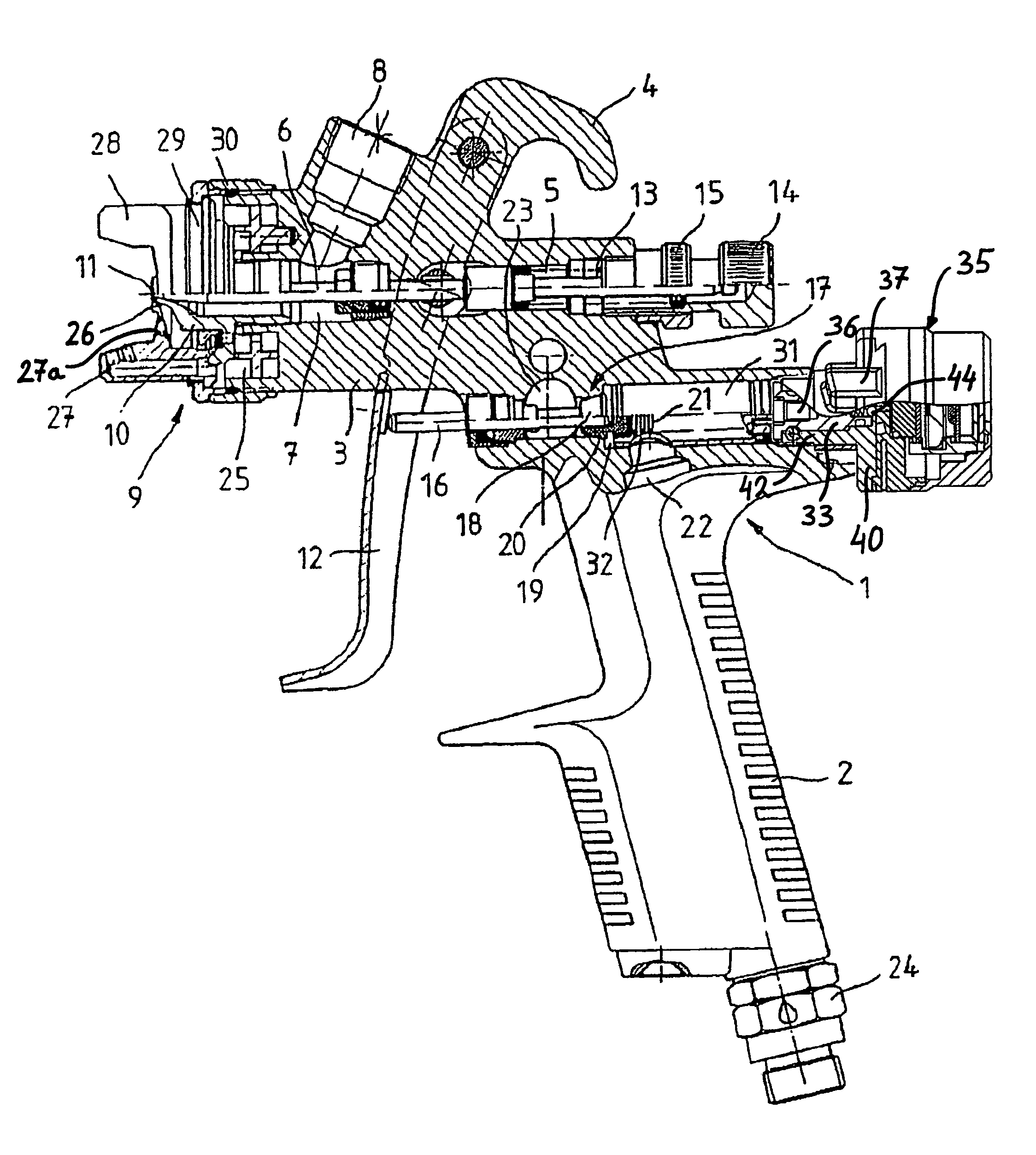
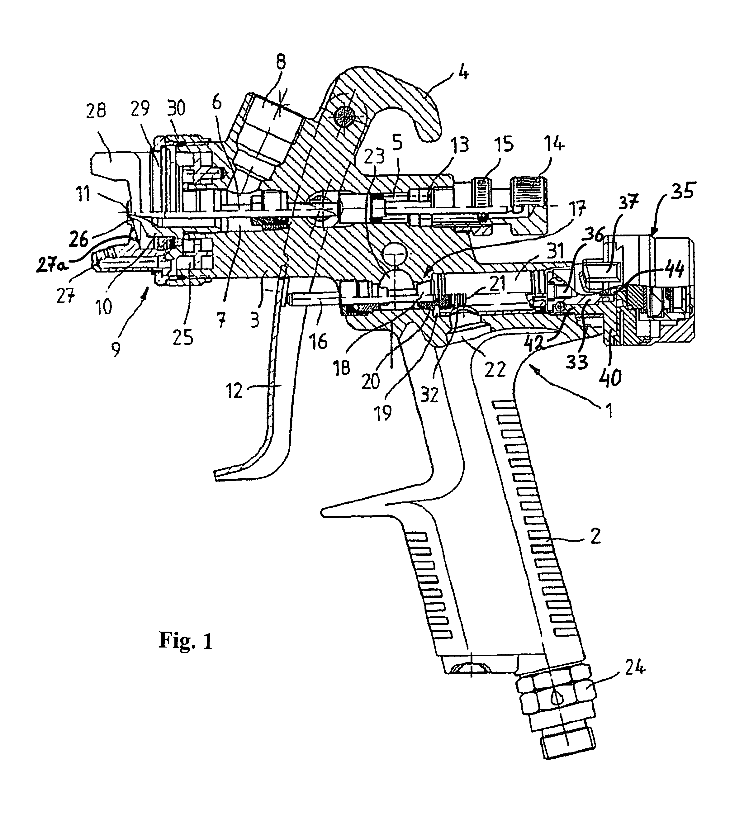
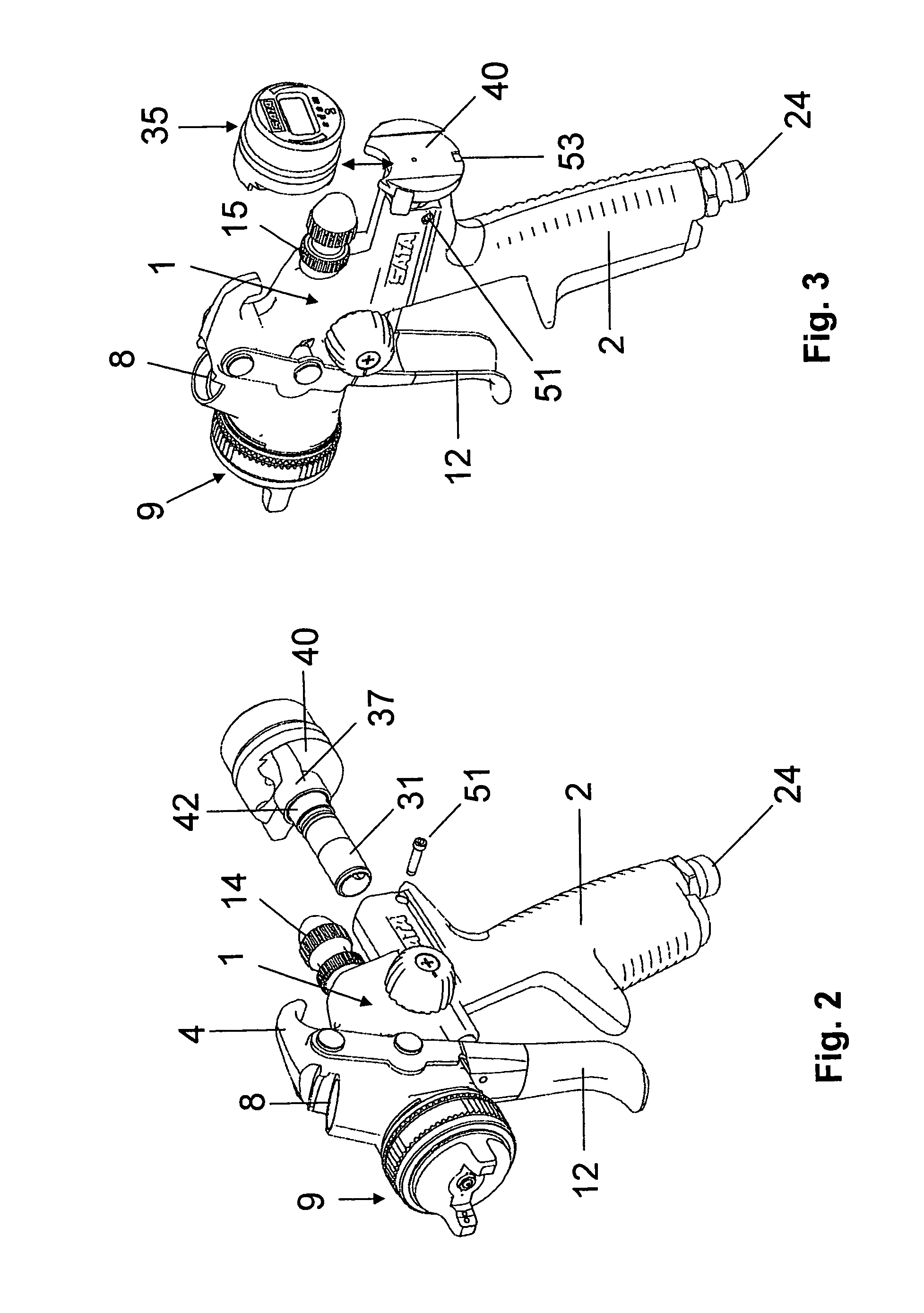
[0021]The spray gun shown in FIGS. 1-3 contains a gun body 1 with a grip 2 and an upper part 3, on which a suspension hook 4 is formed. A passage borehole 5, which is continuous from front to back and is multiply graduated and in which a nozzle needle 6 is conducted axially, so that it can be displaced, runs through the upper part 3. In a front area, the passage borehole 5 forms an expanded holder space 7, into which an inclined inflow borehole 8 opens for the mounting of a paint-holding container, which is not depicted. On the front end of the passage borehole 5, a nozzle arrangement 9 is mounted, which contains a fixable paint nozzle 10, by means of a thread, on the upper part 3 of the gun body 1. The paint nozzle 10 has a nozzle borehole 11, on its front end, which, together with a tapering front end part of the nozzle needle 6, which can move axially via an actuation lever 12, forms a regulatable inflow for the paint, varnish, or the like. The actuation lever 12 is connected wit...


PUM

PropertyMeasurementUnit
angleaaaaaaaaaa
angleaaaaaaaaaa
pressureaaaaaaaaaa

Abstract

The invention relates to a spray gun comprising a gun body (1), a nozzle arrangement (9) arranged on said gun body (1), a compressed air supply channel (22, 23) which is arranged in the gun body (1) and which comprises a valve arrangement (17) for controlling the compressed air supply to the nozzle arrangement (9), a device (31, 33, 37, 42, 40) for controlling the compressed air supply, and a pressure measuring device (35) for recording and displaying the pressure in the compressed air channel (22). Said invention is characterized in that said pressure measuring device (35) is secured in a removable manner to the device (31, 33, 37, 42, 40) for controlling the compressed air supply.

Description

FIELD OF THE INVENTION[0001]The invention concerns a spray gun and a testing air cap for a spray gun.BACKGROUND OF THE INVENTION[0002]Such a spray gun is known from EP 1 294 490 B1. With this spray gun with a gun body, a nozzle arrangement on the gun body, a compressed air supply channel arranged in the gun body, with a valve arrangement for the control of the supply of the compressed air for the nozzle arrangement, and a device for regulation of the supply of compressed air, a pressure measuring device for the recording and display of the pressure in the compressed air supply channel is integrated into the device for regulation of the supply of compressed air. The pressure measuring device is thereby accommodated in a housing, wherein the housing is appropriately designed as a turning knob and in this way, the function of an adjustment element is exerted, with which the compressed air supplied to the nozzle arrangement can be regulated.[0003]The disadvantage in this arrangement is ...

Claims


Application Information

Patent Timeline
Patent Type & Authority Patents(United States)
IPC IPC(8): B67D7/08G01L7/00B67D7/56G01P3/00B05B7/12B05B12/00G01L19/00
CPCB05B12/008B05B7/12G01L19/0007
Inventor BROSE, JENSTSCHAN, ALEXANDER
Owner SATA GMBH & CO KG
Why Eureka
Try Eureka