Control circuit for an electric motor having a power-supply control device

a control circuit and electric motor technology, applied in the field of electric motors, can solve the problems of difficult to achieve high transmission precision of analog signals via galvanic isolation, difficult to achieve high precision of analog signals, and special sensitive magnetic sensors, so as to avoid the placement of complex and complex elements, reduce manufacturing costs, and avoid the effect of complex placemen

Active Publication Date: 2014-10-14
ETEL SA
View PDF4 Cites 3 Cited by
  • Summary
  • Abstract
  • Description
  • Claims
  • Application Information

AI Technical Summary

Benefits of technology

[0006]Example embodiment of the present invention provide an efficient and precise control circuit, and in doing so, limit manufacturing costs, especially by avoiding the placement of complex and expensive elements in the control circuit.
[0013]Due to the characteristics of the control circuit, selected measuring devices make it possible to obtain a very precise measurement of the supply current in the phase considered. For reasons of the galvanic isolation, this selection is generally disregarded. Therefore, the system described herein responds in a meaningful manner to the specific problem, by providing a galvanic separating element (especially an optocoupler) between the device for measuring the current of the phase and the electronic control unit. In order, first of all, to ensure high precision in the signal transmission via the optocoupler, and then to lower the costs of the element, it is provided to dispose the galvanic separating element downstream of the analog-to-digital converter such that a digital signal is transmitted via it. A simple optocoupler allows precise transmission of a digital signal, which is not the case for an analog signal. In addition, a floating low voltage is provided in the high-voltage zone in order, in particular, to supply the analog-to-digital converter.
[0015]Accordingly, the analog-to-digital converter receives a measuring signal that corresponds to the difference between the measured current and the setpoint value, that is, a signal whose value lies below that of the measured current. One is thus able to obtain high precision in the conversion of the measured analog signal into digital form for the electronic control unit with a more favorable converter with “10 or 12 bit” or with “16 bit” for a very high resolution. In addition, the analog subtractor may be disposed in the high-voltage zone in order to obtain the advantages of the analog-to-digital converter being upstream of the galvanic separating element. One has therefore taken the subtractor, usually provided in the electronic control unit, out of the low-voltage zone and replaced it by an analog subtractor in the high-voltage zone and supplied it with the floating low voltage made available in this high-voltage zone. This configuration still requires the provision of the setpoint value for the supply voltage, which is generated by the electronic unit in the low-voltage zone as opposed to the high voltage, and to convert that digital signal into a purely analog setpoint value in order to make it available to the analog subtractor. By again disposing a galvanic isolating element between the electronic unit and a digital-to-analog converter, one obtains high precision for the analog setpoint value and the configuration of the relatively simple and advantageous elements. Even though this configuration may appear complex due to the necessity of a multitude of specific elements, especially due to the addition of a galvanic separating element and a digital-to-analog converter, it guarantees very precise regulation of the current and actually a very effective control of the electric motor without the necessity of a complex or costly element.

Problems solved by technology

It is noteworthy that such an element is relatively complex, and that high transmission precision of an analog signal via a galvanic isolation can only be achieved with difficulty.
However, such magnetic sensors are especially sensitive with regard to ambient magnetic fields which produce errors in the measurement.
The signal-to-noise ratio is disadvantageous with such magnetic sensors to the extent that the precision of the current measurement in the phase is thereby impaired.
As mentioned above, galvanic separating device 16 is relatively complex, and the precision of the transmission of analog signal SC via the device is not particularly high.
This presents a further problem concerning the precision of the control signal, such that the transmission of the modulated signal produces a parasitic signal which must be filtered in analog fashion at the input of the power amplifier.
This filtering is simplified by the selection of an increased frequency for the transmission of the signal, but is to the detriment of the resolution of the modulation of the pulse width, which becomes inadequate in so far as explained in the introduction to the U.S. Pat. No. 7,692,465.
In addition, the filtering may be reflected in phase 2 itself, if a power amplifier is used in the switching mode; however, this option is not compatible with the demands with regard to precision placed on the present practical application.
The control of the electric motor explained above raises precision problems, first of all, in measuring signal IM* generated by electronic control unit 6, and subsequently in control signal SC generated by the electrical supply of the motor.

Method used


Image

  • Control circuit for an electric motor having a power-supply control device
  • Control circuit for an electric motor having a power-supply control device
  • Control circuit for an electric motor having a power-supply control device

Examples


Embodiment Construction

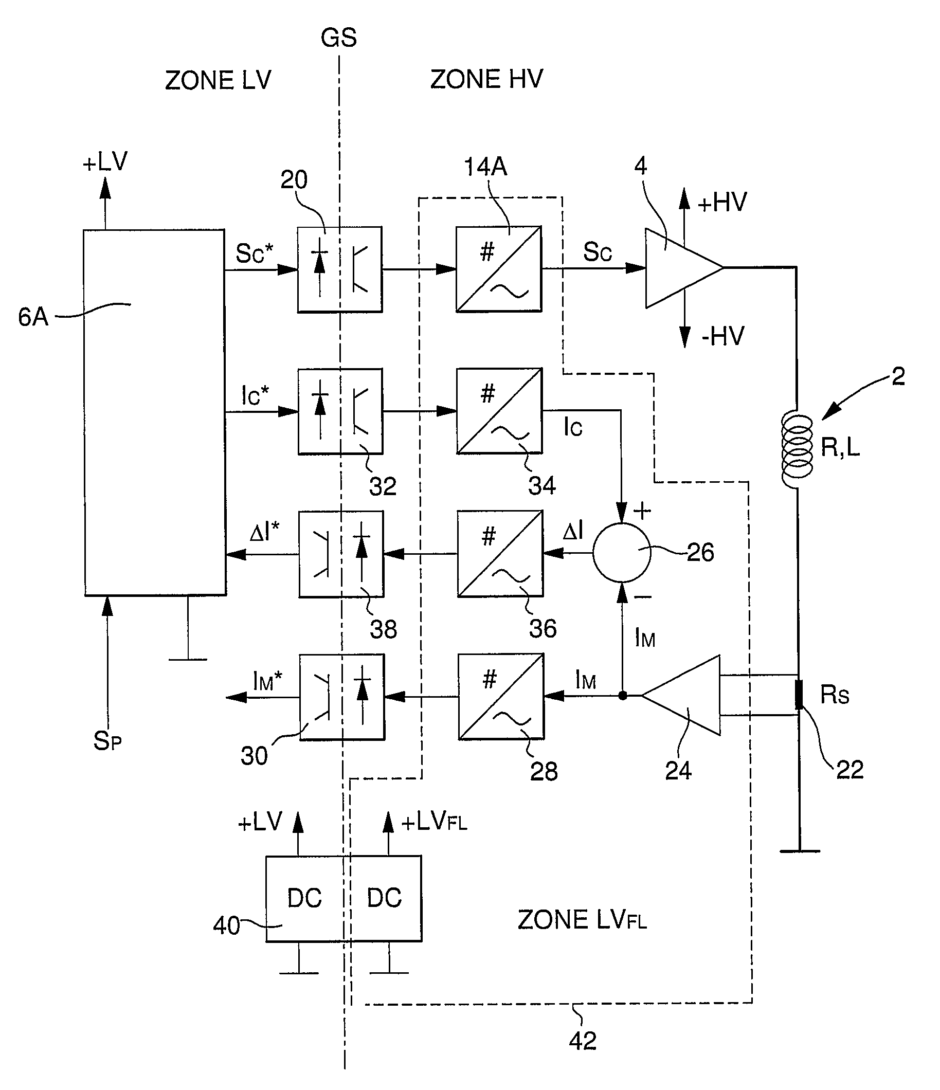
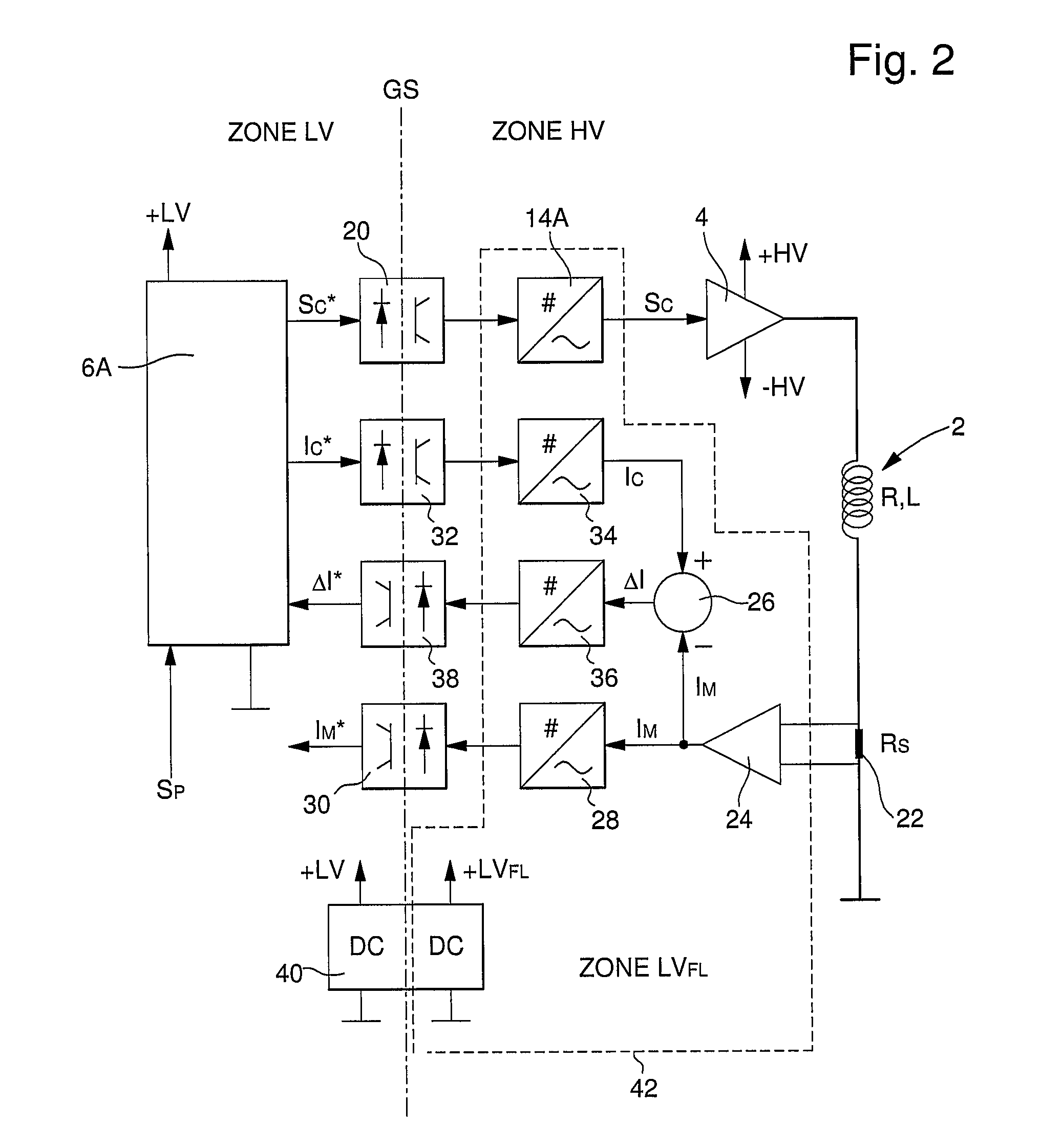
[0020]FIG. 2 schematically illustrates a control circuit of an electric motor according to an example embodiment of the present invention. The motor is represented by its phase 2. The supplies of the high voltage +HV, −HV are provided in a conventional manner and are formed by a power amplifier 4, for example. The power amplifier may be operated in linear mode or in switchover mode. However, in view of the high demands on the precision of the present practical application, a linear operation is preferred. Electronic control unit 6A is supplied with low voltage and is located in a low-voltage zone, “zone LV,” galvanically isolated from the high-voltage zone, “zone HV,” where phase 2 and its supply 4 are located, as required by prevailing safety standards for high voltages above a predefined limit, e.g., 48 volts.

[0021]Electronic control unit 6A provides a digital control signal SC* which, according to example embodiments, is initially made available to a galvanic separating element 2...


PUM


Abstract

The control circuit of an electric motor, which has at least one phase supplied with high voltage and has a defined high-voltage zone, is provided with a control for the supply current of the phase with a setpoint-value current, and has devices for measuring the supply current which generate a first analog signal whose value corresponds to the measured current, an electronic control unit being disposed in a low-voltage zone, and having an analog-to-digital converter for converting the first analog signal or another analog signal acting as the first analog signal, into a corresponding digital signal which is supplied to the electronic control unit. The measuring devices are formed by a bleeder resistor, which is disposed in series with the phase, as well as by a differential amplifier whose two inputs, respectively, are connected to two contacts of the bleeder resistor. The analog-to-digital converter is located in the high-voltage zone a galvanic separating element is situated between the analog-to-digital converter and the electronic control unit. The control circuit has, inter alia, a voltage converter which, within the high-voltage zone, provides a floating low voltage which supplies the analog-to-digital converter.

Description

FIELD OF THE INVENTION[0001]The present invention relates to the special field of electric motors, especially linear motors, and in particular, those whose electric-motor control with a control device permits precise driving of the motor.BACKGROUND INFORMATION[0002]The electric motors which are used in machine tools and in various industrial installations are often controlled such that a predefined setpoint-value position is reached. In this context, a main control loop is implemented in the control of such electric motors in order to adjust an actual position of the moving part of the motor to a setpoint-value position. The difference in position is processed via an electronic control unit, which determines a setpoint value for the supply current. The supply of the motor is therefore designed to feed the motor (each of its phases) so as to generate a supply current that corresponds with the setpoint-value current. In order to ensure the precision of the intended movement, it is adv...

Claims


Application Information

Patent Timeline
Patent Type & Authority Patents(United States)
IPC IPC(8): G05B11/00H02P25/06
CPCH02P25/06
Inventor BLANC, DIDIERCOLEMAN, RALPHVAUCHER, JEAN-MARCFROIDEVAUX, CLAUDE
Owner ETEL SA
Why Eureka
Try Eureka