Process and apparatus for fluid catalytic cracking

a technology of fluid catalytic cracking and process, applied in the direction of physical/chemical process catalysts, gas-gas reaction processes, furnaces, etc., can solve the problems of increasing maintenance downtime, and achieve the effect of reducing pressure variances

Active Publication Date: 2014-10-21
UOP LLC
View PDF18 Cites 25 Cited by
  • Summary
  • Abstract
  • Description
  • Claims
  • Application Information

AI Technical Summary

Benefits of technology

[0008]The embodiments disclosed herein can reduce pressure variances by moving a spent second catalyst return from the first stage to the lower second stage of a regeneration vessel. As a result of lowering the spent second catalyst return, additional standpipe head can be obtained thus more closely matching the pressure differentials of the other valves of the apparatus.DEFINITIONS

Problems solved by technology

This shortcoming can increase maintenance downtimes, particularly due to valves having different wear rates, the unit typically is shutdown to allow replacement of individual valves.

Method used


Image

  • Process and apparatus for fluid catalytic cracking
  • Process and apparatus for fluid catalytic cracking
  • Process and apparatus for fluid catalytic cracking

Examples


Embodiment Construction

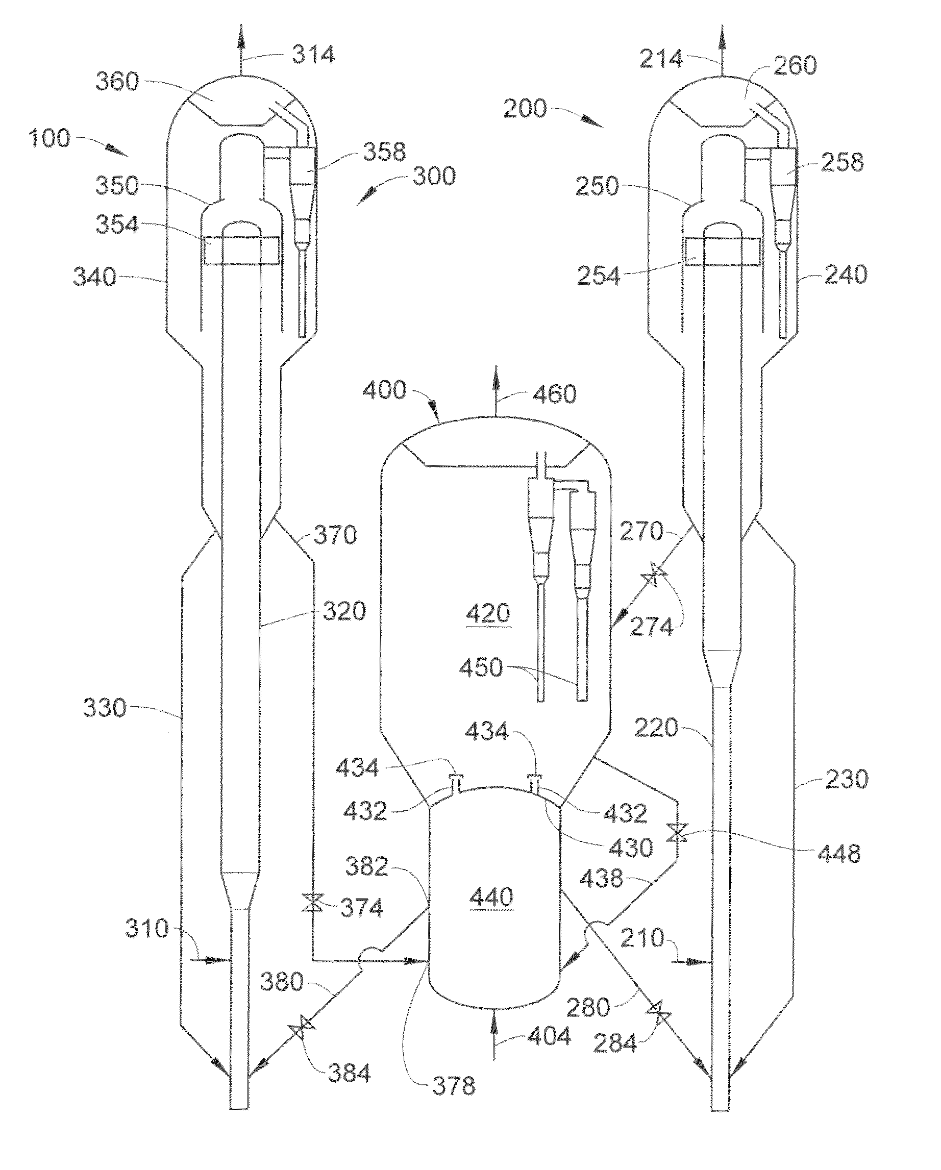
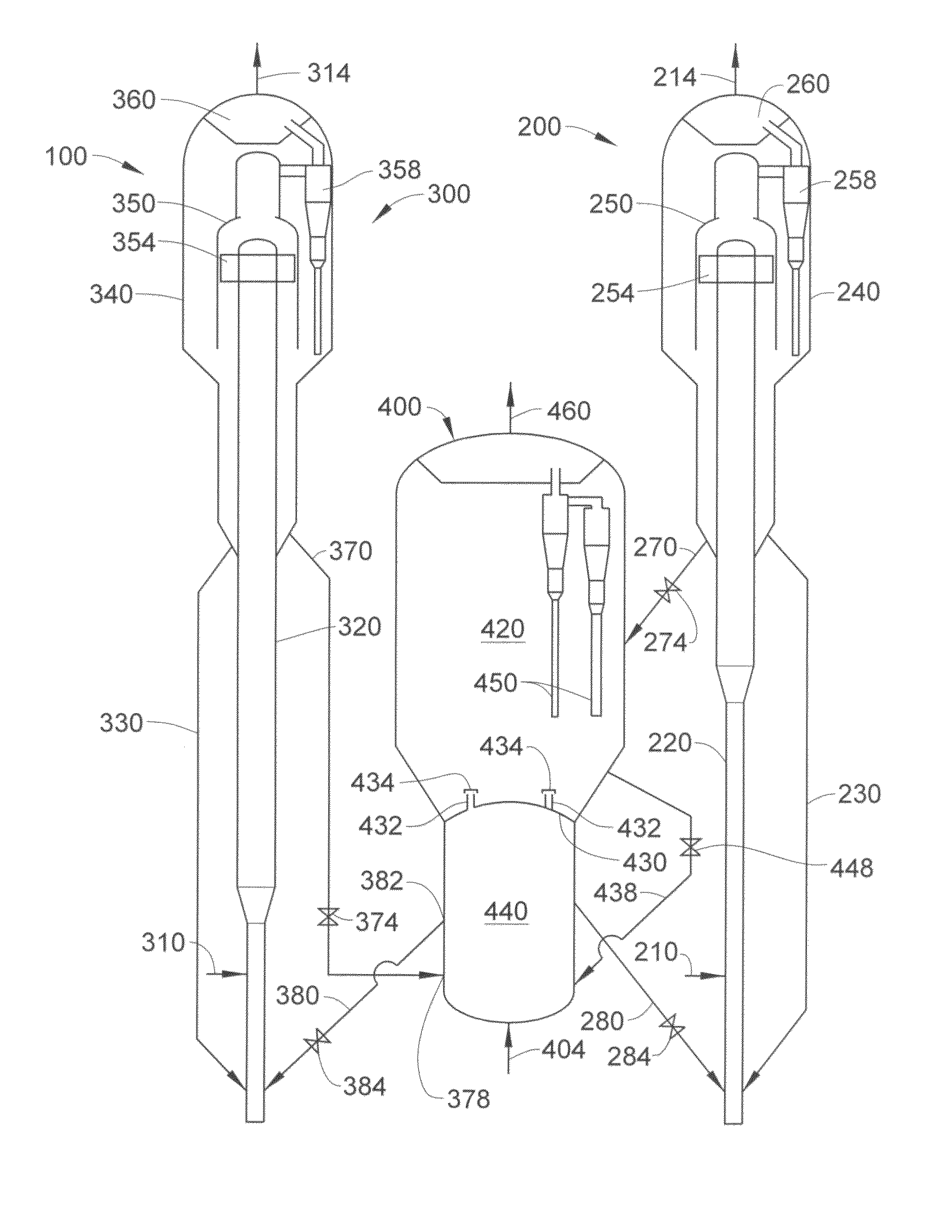
[0020]Referring to the FIGURE, an exemplary fluid catalytic cracking apparatus 100 can include a first riser reactor 200, a second riser reactor 300, and a regeneration vessel 400. Generally, the first riser reactor 200 can include a first riser 220 terminating in a first reaction vessel 240. The first riser 220 can receive a feed 210 that can have a boiling point range of about 180-about 800° C. Typically, the feed 210 can be at least one of a gas oil, a vacuum gas oil, an atmospheric gas oil, and an atmospheric residue. Alternatively, the feed 210 can be at least one of a heavy cycle oil and a slurry oil. Generally, the feed 210 can be a fresh feed, or receive a recycle stream from, for example, a product separation zone having one or more distillation columns.

[0021]Generally, the feed 210 can be provided at any suitable height on the first riser 220, generally above a lift gas provided at the bottom of the first riser 220. The feed 210 may be provided at a distance sufficient to ...


PUM

PropertyMeasurementUnit
pressureaaaaaaaaaa
pressureaaaaaaaaaa
boiling pointaaaaaaaaaa

Abstract

One exemplary embodiment can be a process for fluid catalytic cracking. The process can include sending a first catalyst from a first riser reactor and a second catalyst from a second riser reactor to a regeneration vessel having a first stage and a second stage. The first catalyst may be sent to the first stage and the second catalyst may be sent to the second stage of the regeneration vessel. Generally, the first stage is positioned above the second stage.

Description

FIELD OF THE INVENTION[0001]This invention generally relates to a process and an apparatus for fluid catalytic cracking.DESCRIPTION OF THE RELATED ART[0002]Catalytic cracking can create a variety of products from larger hydrocarbons. Often, a feed of a heavier hydrocarbon, such as a vacuum gas oil, is provided to a catalytic cracking reactor, such as a fluid catalytic cracking reactor. Various products may be produced from such a system, including a gasoline product and / or light product such as propene and / or ethene.[0003]In such systems, a single reactor or a dual reactor can be utilized. Although additional capital costs may be incurred by using a dual reactor system, one of the reactors can be operated to tailor conditions for maximizing products, such as light alkenes including propene and / or ethene.[0004]In dual reactor systems, valves are often utilized for transferring catalyst to and from the riser reactor and the regenerator. However, the pressure differentials on these val...

Claims


Application Information

Patent Timeline
Patent Type & Authority Patents(United States)
IPC IPC(8): C10G11/05C10G51/06B01J8/24B01J8/26B01J8/18C10G11/18
CPCB01J8/0055B01J8/26C10G11/182B01J29/90B01J38/06C10G11/00B01J21/20B01J8/08
Inventor PALMAS, PAOLO
Owner UOP LLC
Why Eureka
Try Eureka