Pressure release valve assembly for pressure cooker

a technology for pressure cookers and valve assemblies, applied in the field of pressure cookers, can solve the problems of undesired consequences, omnipresent explosion risk, and very real risk, and achieve the effect of convenient threading connection

Active Publication Date: 2014-10-28
HASEGAWA TOM HIROSHI
View PDF13 Cites 70 Cited by
  • Summary
  • Abstract
  • Description
  • Claims
  • Application Information

AI Technical Summary

Benefits of technology

[0006]Accordingly, it is an object of the present invention to provide a pressure release valve assembly that can be securely attached to the lid of a pressure cooker and removable and restorable with the safety during the use is assured.
[0019]With the structure above, the pressure intake unit that includes the filtering cap that is formed as a single unit comprising the pressure outlet tube, the connecting plug in substantially a truncated conical shape, the pressure intake tube, and the filtering cap. Accordingly, unless this single pressure intake unit is connected to the pressure control unit, a pressure control valve is not formed or provided on a lid of the pressure cooker, and thus a pressure cooker is not configured; and as a result, an incident that a user forget to attach the filtering cap, which is the safety cap, or fail to completely attach the filtering or safety cap to the lid of a pressure cooker can be prevented.
[0020]Furthermore, in the above structure, the pressure outlet portion of the pressure outlet tube of the pressure intake unit is externally threaded, so that the cylindrical pressure release casing of the pressure control unit can be easily threadedly connected at its bottom to the pressure outlet tube of the pressure intake unit.

Problems solved by technology

Unfortunately, there is an omnipresent risk of explosion caused by too much pressure inside the pot.
This risk is very real because a pressure cooker prohibits the free circulation of air between the interior and the exterior of the pot and cooks food under high-pressure and high-temperature conditions.
Nonetheless, users can remove the safety cap from the lid of a pressure cooker for the purpose of cleaning; as a result, a user could forget to put the safety cap back on the pressure release valve or fail to completely attach the safety cap back on the pressure release valve, leading to eventual undesired consequences.

Method used


Image

  • Pressure release valve assembly for pressure cooker
  • Pressure release valve assembly for pressure cooker
  • Pressure release valve assembly for pressure cooker

Examples


Embodiment Construction

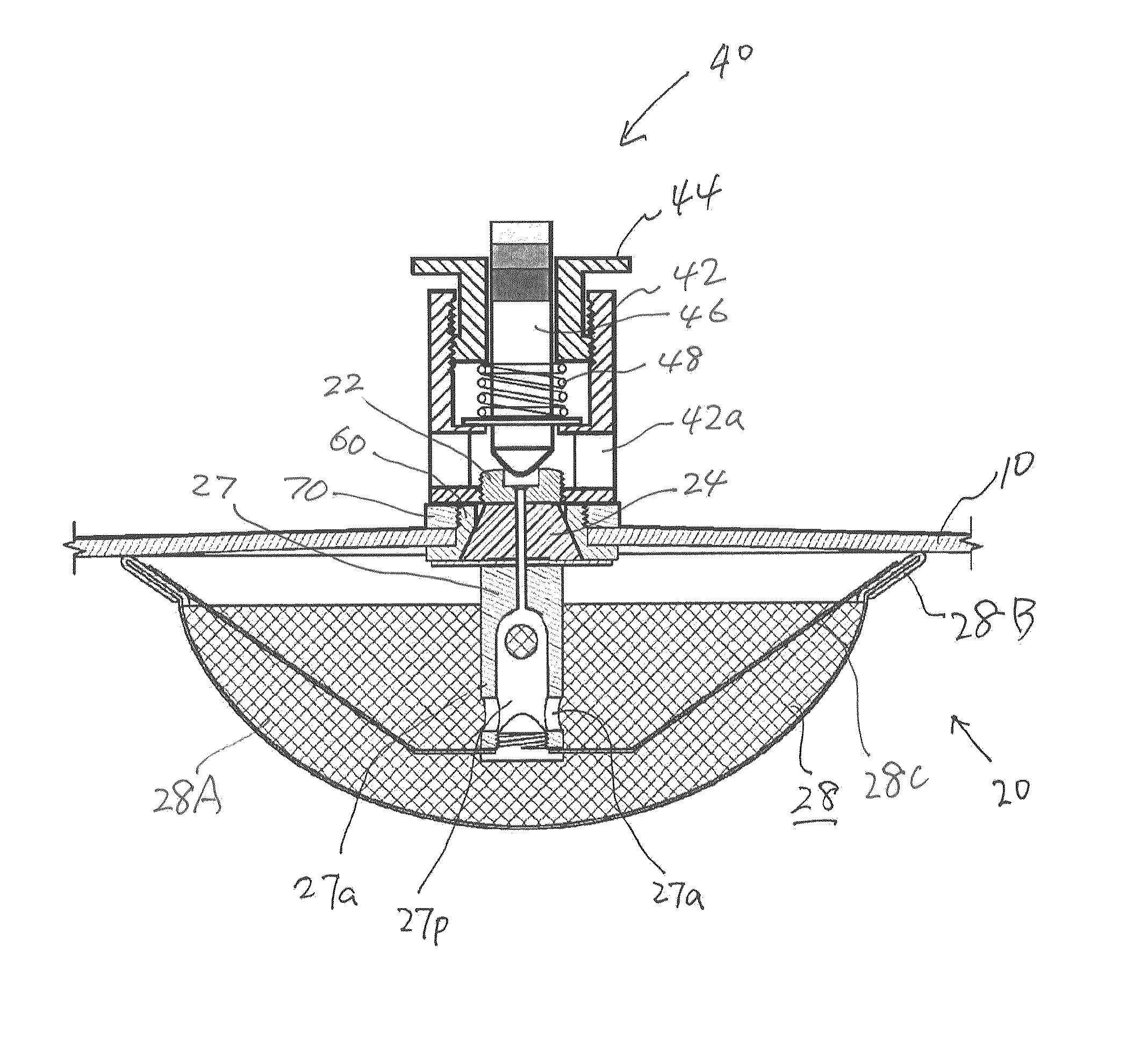
[0030]The pressure release valve assembly according to the present invention is, as shown in FIG. 1, comprised of two units that comprises a pressure intake unit 20 and a pressure control unit 40 which are thread-connected to each other with an annular attachment nut 60 in between so that the pressure intake unit 20 is inside of or underneath the lid 10 of a pressure cooker and the pressure control unit 40 is outside of or on the lid 10.

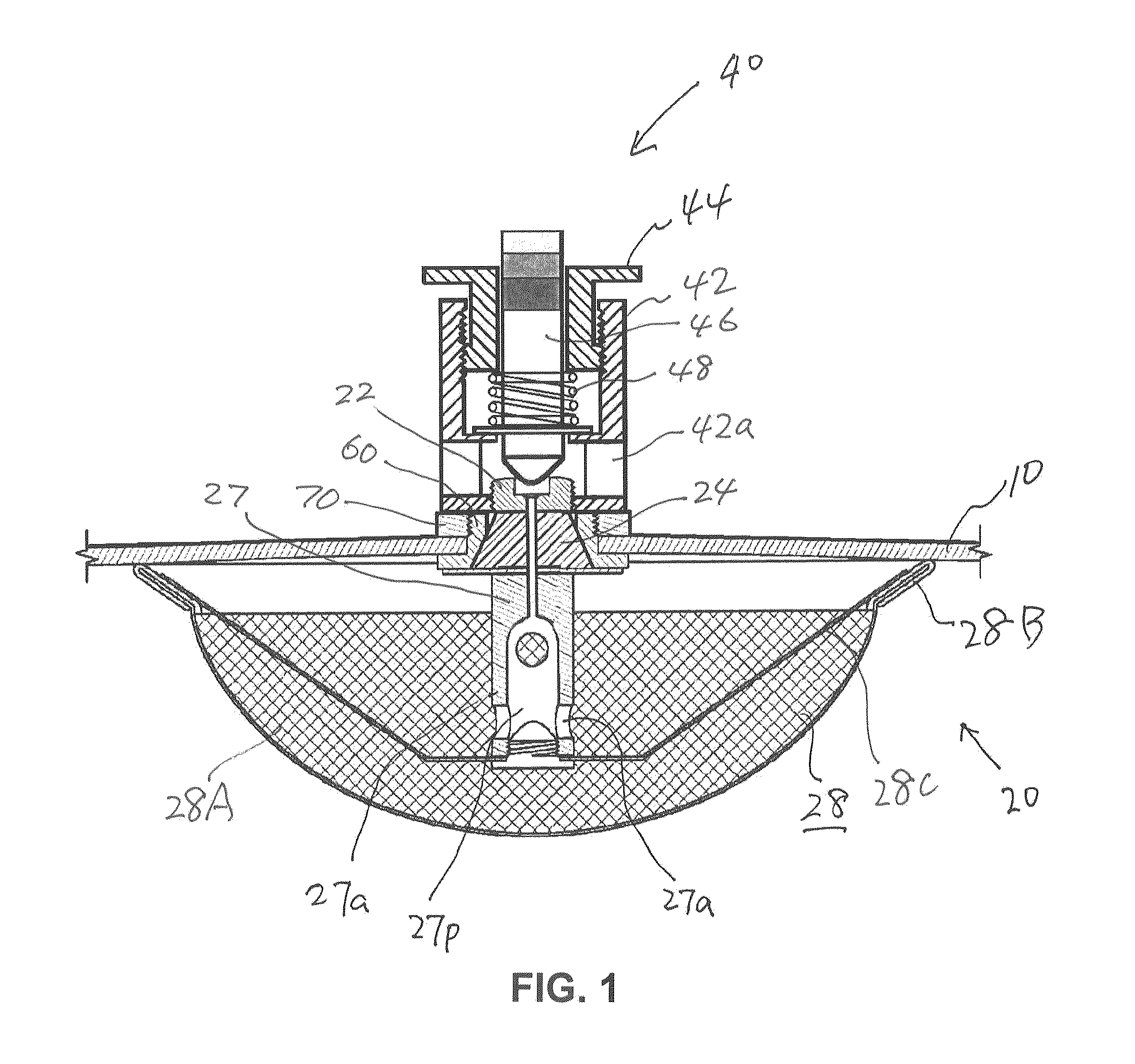
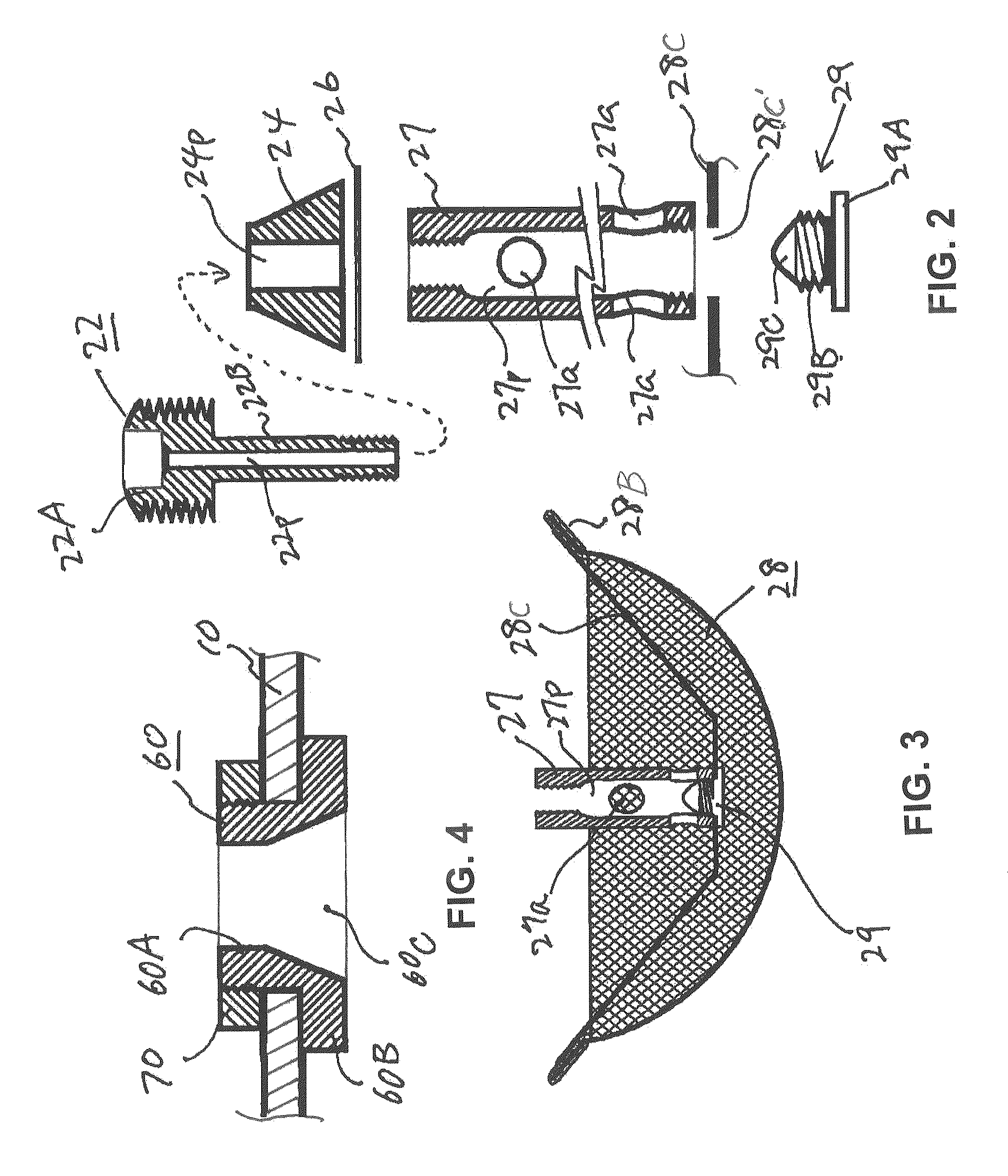
[0031]The pressure intake unit 20 is a one-piece unit that is substantially comprised of a pressure outlet tube 22, a connecting plug 24, a securing plate 26, a pressure intake tube 27 and a filtering cap 28.

[0032]The pressure outlet tube 22, as seen from FIG. 3, includes a pressure outlet portion 22A at the top and a main tube portion 22B that is formed therein with an axially extending pressure outlet path 22p at the center. The pressure outlet portion 22A of the pressure outlet tube 22 is eternally threaded, and so is the bottom portion of the mai...


PUM


Abstract

A pressure release valve assembly for a pressure cooker including a pressure intake unit provided inside of (or under) the lid of a pressure cooker and a pressure control unit connected to the pressure intake unit and provided outside of the lid. The pressure intake unit includes a pressure outlet tube, a connecting plug substantially in a truncated conical shape and connected to the pressure outlet tube with the connecting plug in between, a pressure intake tube connected to the pressure outlet tube, and a filtering cap attached to the pressure intake tube; and the pressure control unit includes a cylindrical pressure release casing, a tubular pressure control element threadedly connected to the inside of the pressure release casing, a valve plunger provided inside the tubular pressure control element, and a pressure spring installed between the pressure control element and an externally expanding supporting flange of the valve plunger.

Description

BACKGROUND OF THE INVENTION[0001]1. Field of the Invention[0002]The present invention relaters to a pressure cooker and more specifically to a pressure release valve assembly used in a pressure cooker.[0003]2. Prior Art[0004]A pressure cooker that utilizes high-temperature and high-pressure steam to cook food inside the pot has been well known and used widely. Unfortunately, there is an omnipresent risk of explosion caused by too much pressure inside the pot. This risk is very real because a pressure cooker prohibits the free circulation of air between the interior and the exterior of the pot and cooks food under high-pressure and high-temperature conditions. So as to prevent this risk, several different counter measures have been taken, including using sturdier materials to construct pots, utilizing a timer to control the length of heating time, installing a pressure gauge to monitor the atmospheric pressure inside, installing a pressure release valve, and / or installing a safety ca...

Claims


Application Information

Patent Timeline
Patent Type & Authority Patents(United States)
IPC IPC(8): A47J36/06F16K37/00A47J27/09F16K15/06F16K17/06
CPCA47J27/09F16K21/04Y10T137/8275Y10T137/7878F16K37/0058Y10T137/7934Y10T137/7837F16K15/063A47J27/092A47J27/08
Inventor HASEGAWA, TOM, HIROSHI
Owner HASEGAWA TOM HIROSHI
Why Eureka
Try Eureka