Riveting assembly

a technology of riveting assembly and riveting piece, which is applied in the direction of threaded fasteners, manufacturing tools, mechanical devices, etc., can solve the problems of deformation of the riveting piece, workpieces may easily fall off, weak connection strength, etc., and achieves improved anti-torque capability, easy rotation, and improved anti-tensile capability.

Active Publication Date: 2014-10-28
CHICONY ELECTRONICS
View PDF8 Cites 3 Cited by
  • Summary
  • Abstract
  • Description
  • Claims
  • Application Information

AI Technical Summary

Benefits of technology

[0008]In order to solve the problems of the prior art, the disclosure provides an improved riveting assembly, in which a plurality of notches are formed at a riveting hole of a base plate of the riveting assembly. After a riveting piece passes through the riveting hole to be riveted to the base plate, portions of the riveting piece corresponding to the notches are stamped, thereby engaging the portions of the riveting piece with the notches. Therefore, when being impacted, the riveting piece will not be easily rotated relative to the base plate. In other words, the riveting assembly of the disclosure can provide better anti-torque capability between the riveting piece and the base plate. Furthermore, a secondary processing (i.e. a stamping process) can be performed onto the riveting piece after the riveting piece is riveted to the base plate, thereby further improving anti-tensile capability between the riveting piece and the base plate. In the disclosure, the riveting assembly primarily adopts a stud as the riveting piece.

Problems solved by technology

However, thickness of the chassis plates is generally small, so that the screws may easily escape from the threaded holes due to small contact areas between the screws and the chassis plates which result in weak connection strength.
However, a deformed portion of the riveting piece for being riveted to the workpiece may easily fall off from the workpiece while being rotated relative to the workpiece or deformed again due to an external impact.
In other words, the conventional riveting manner cannot provide better anti-torque and anti-tensile capabilities.
Therefore, when being impacted, the riveting piece will not be easily rotated relative to the base plate.

Method used


Image

  • Riveting assembly
  • Riveting assembly
  • Riveting assembly

Examples


Embodiment Construction

[0031]Reference will now be made in detail to the present embodiments of the disclosure, examples of which are illustrated in the accompanying drawings. Wherever possible, the same reference numbers are used in the drawings and the description to refer to the same or like parts.

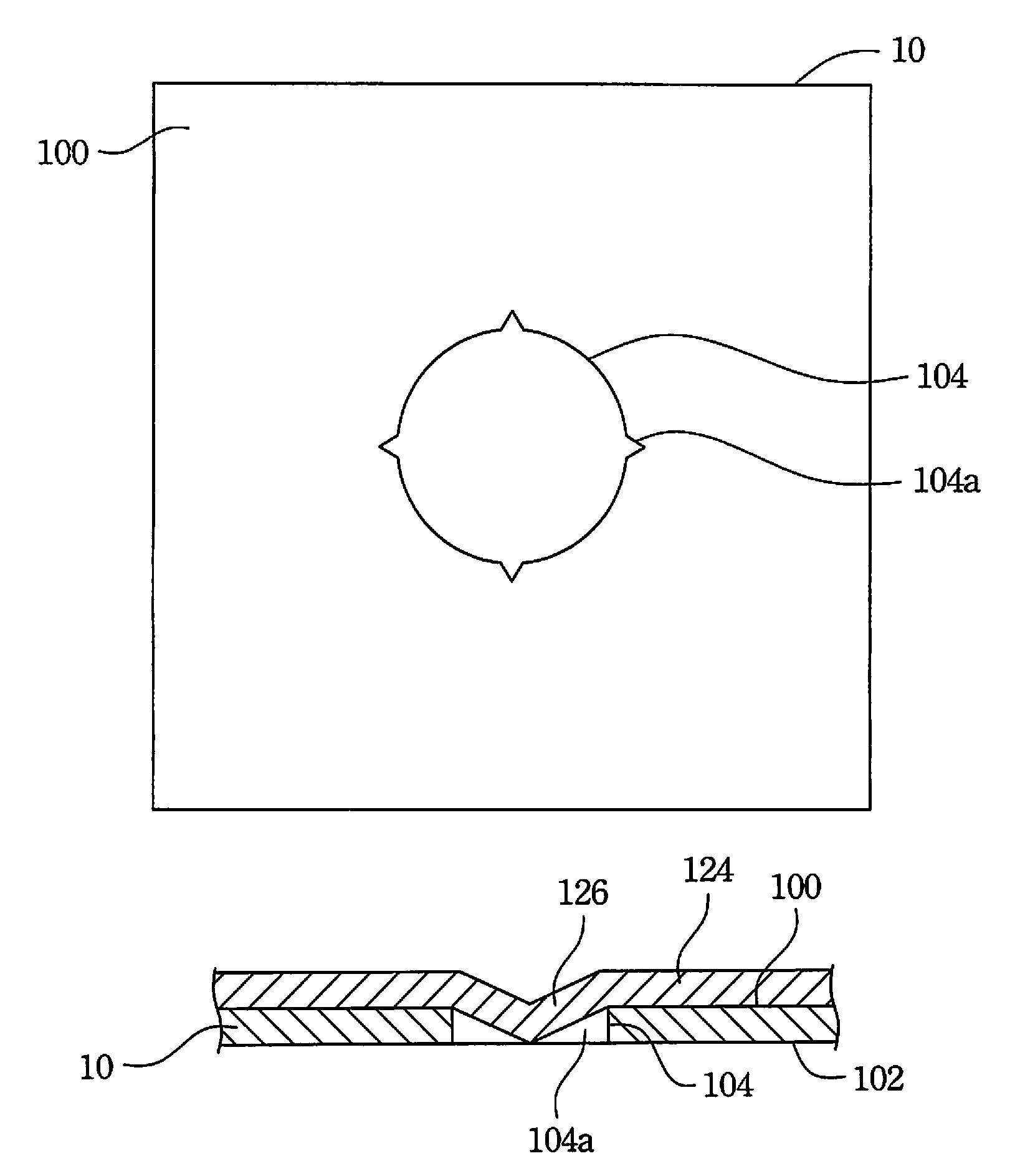
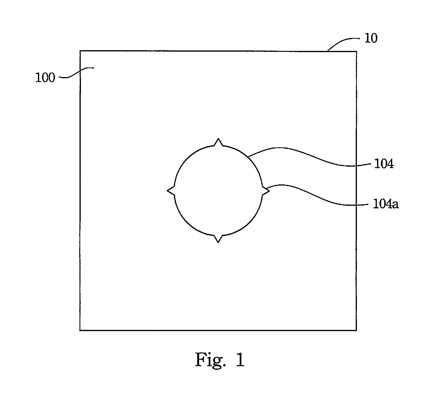
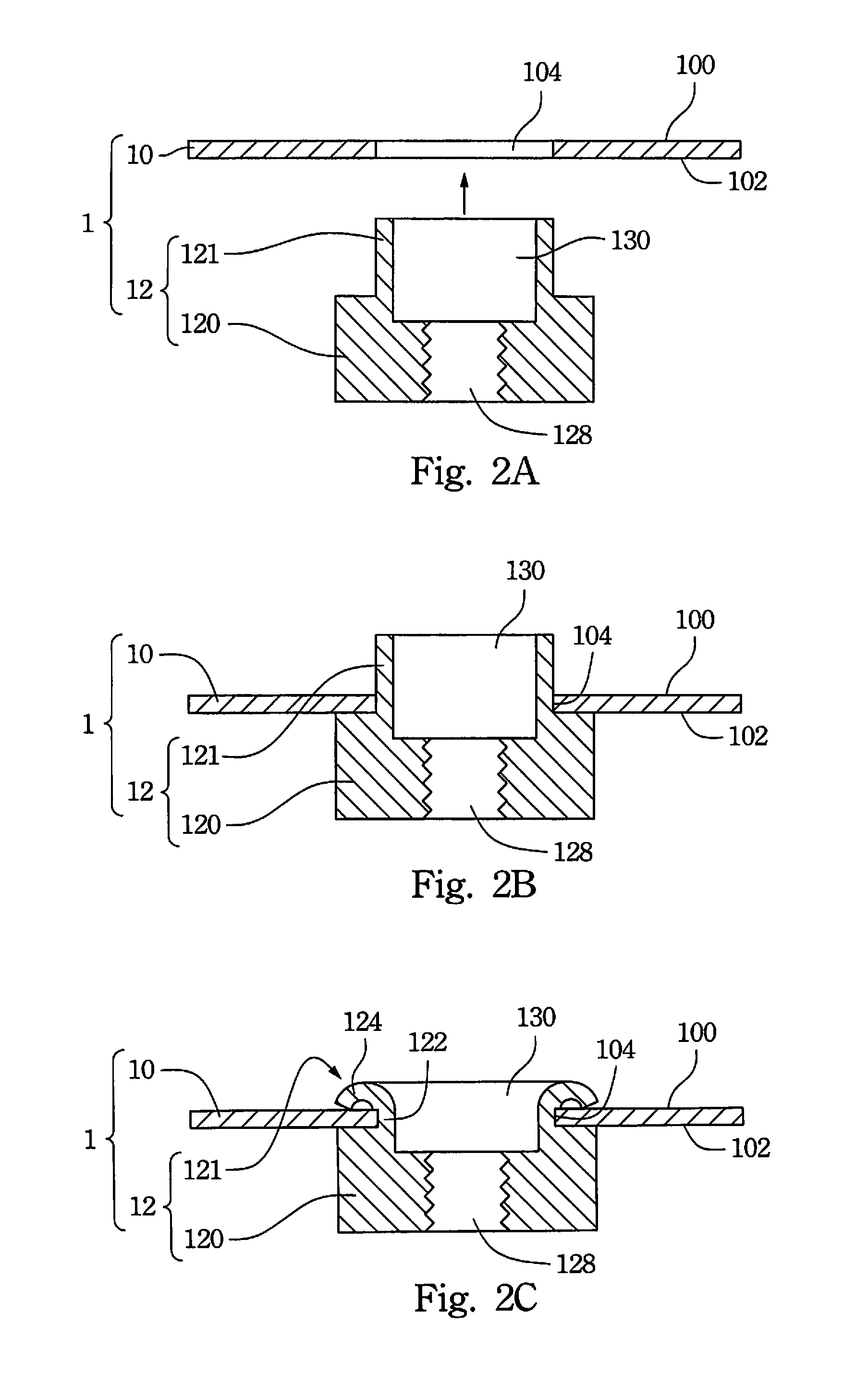
[0032]FIG. 1 is a top view of a base plate 10 of a riveting assembly 1 according to an embodiment of the disclosure. FIG. 2A is a cross-sectional view of the riveting assembly 1 according to an embodiment of the disclosure, in which a stud 12 has not been engaged with the base plate 10.

[0033]As shown in FIG. 1 and FIG. 2A, the riveting assembly 1 of the disclosure firmly fixes the stud 12 to the base plate 10, but the disclosure is not limited in this regard. For example, concepts of the riveting assembly 1 can be applied to an electronic product having a chassis structure (such as a host computer, a DVD player, a VCD player, etc.) for firmly connecting two plates of the chassis structure or connecting a circ...


PUM

PropertyMeasurementUnit
diameteraaaaaaaaaa
thicknessaaaaaaaaaa
connection strengthaaaaaaaaaa

Abstract

A riveting assembly includes a base plate and a stud. The base plate has a first surface, a second surface, and a riveting hole. The riveting hole is communicated with the first surface and the second surface and has at least one notch. The stud includes a main body and a riveting structure. The main body abuts against the second surface and covers the riveting hole. The riveting structure is connected to the main body. The riveting structure protrudes out from the riveting hole to abut against the first surface and to be engaged with the notch. A portion of the base plate is clamped between the main body and the riveting structure.

Description

RELATED APPLICATIONS[0001]This application claims priority to Taiwan Application Serial Number 101217867, filed Sep. 14, 2012, which is herein incorporated by reference.BACKGROUND[0002]1. Technical Field[0003]The present disclosure relates to a riveting assembly, and more particularly, to a riveting assembly for combining a stud with a base plate.[0004]2. Description of Related Art[0005]In a conventional electronic product (e.g., a host computer, a DVD player, a VCD player, etc.) with a chassis structure, a fastening method is generally needed for fixing chassis plates to each other or to a circuit board. The fastening method forms threaded holes on the plates firstly, and then uses screws into the threaded holes for fastening. However, thickness of the chassis plates is generally small, so that the screws may easily escape from the threaded holes due to small contact areas between the screws and the chassis plates which result in weak connection strength. Therefore, a riveting meth...

Claims


Application Information

Patent Timeline
Patent Type & Authority Patents(United States)
IPC IPC(8): F16B13/04
CPCF16B37/065F16B5/04B23P19/063B21J15/04
Inventor TSAI, CHING-CHENG
Owner CHICONY ELECTRONICS
Why Eureka
Try Eureka