Scanning FTIR systems for touch detection

a touch detection and scanning ftir technology, applied in the field of touch detection techniques, can solve the problems of unintentional variation, unintentional variation, and reduction of the impact of tolerances in the illumination arrangement, so as to reduce the footprint reduce the thickness of the touch-sensing apparatus

Inactive Publication Date: 2014-10-28
FLATFROG LAB
View PDF33 Cites 34 Cited by
  • Summary
  • Abstract
  • Description
  • Claims
  • Application Information

AI Technical Summary

Benefits of technology

[0019]The use of plural short sweeps, in contrast to a single full sweep, allows the illumination arrangement, or rather its sweep generating device, e.g. a beam scanner, to be placed closer to the incoupling site. It is realized that this may reduce the impact of tolerances in the illumination arrangement, e.g. tolerances that result in unintended deviations in the direction and / or location of the individual beams during the sweep. The shorter sweep may alternatively, or additionally, be used to relax the performance requirements of the illumination arrangement. Specifically, it may be possible to use simpler / cheaper sweep generating devices.
[0036]In one embodiment, the detection arrangement comprises an elongate light-sensing surface or an array of light-sensing elements arranged parallel to and optically facing the outcoupling site. This enables a compact design of the detection arrangement, since the light-sensing surface / elements may be arranged close to the outcoupling site. The elongate light-sensing surface is suitably arranged to collect all light from the outcoupling site, which calls for time-resolved detection of the light reaching the outcoupling site. The use of an elongate light-sensing surface therefore requires the sub-sweeps to be generated sequentially. The use of an array of light-sensing elements enables spatially resolved detection of the light reaching the outcoupling site. Such use may enable concurrent generation of the sub-sweeps, but will require different beam legs (first, second, etc) to be generated sequentially.

Problems solved by technology

It is realized that this may reduce the impact of tolerances in the illumination arrangement, e.g. tolerances that result in unintended deviations in the direction and / or location of the individual beams during the sweep.
Such variations may be intentional or unintentional.
Unintentional variations may be caused by inaccuracies in the illumination arrangement, e.g. in the sweep generating device.

Method used


Image

  • Scanning FTIR systems for touch detection
  • Scanning FTIR systems for touch detection
  • Scanning FTIR systems for touch detection

Examples


Embodiment Construction

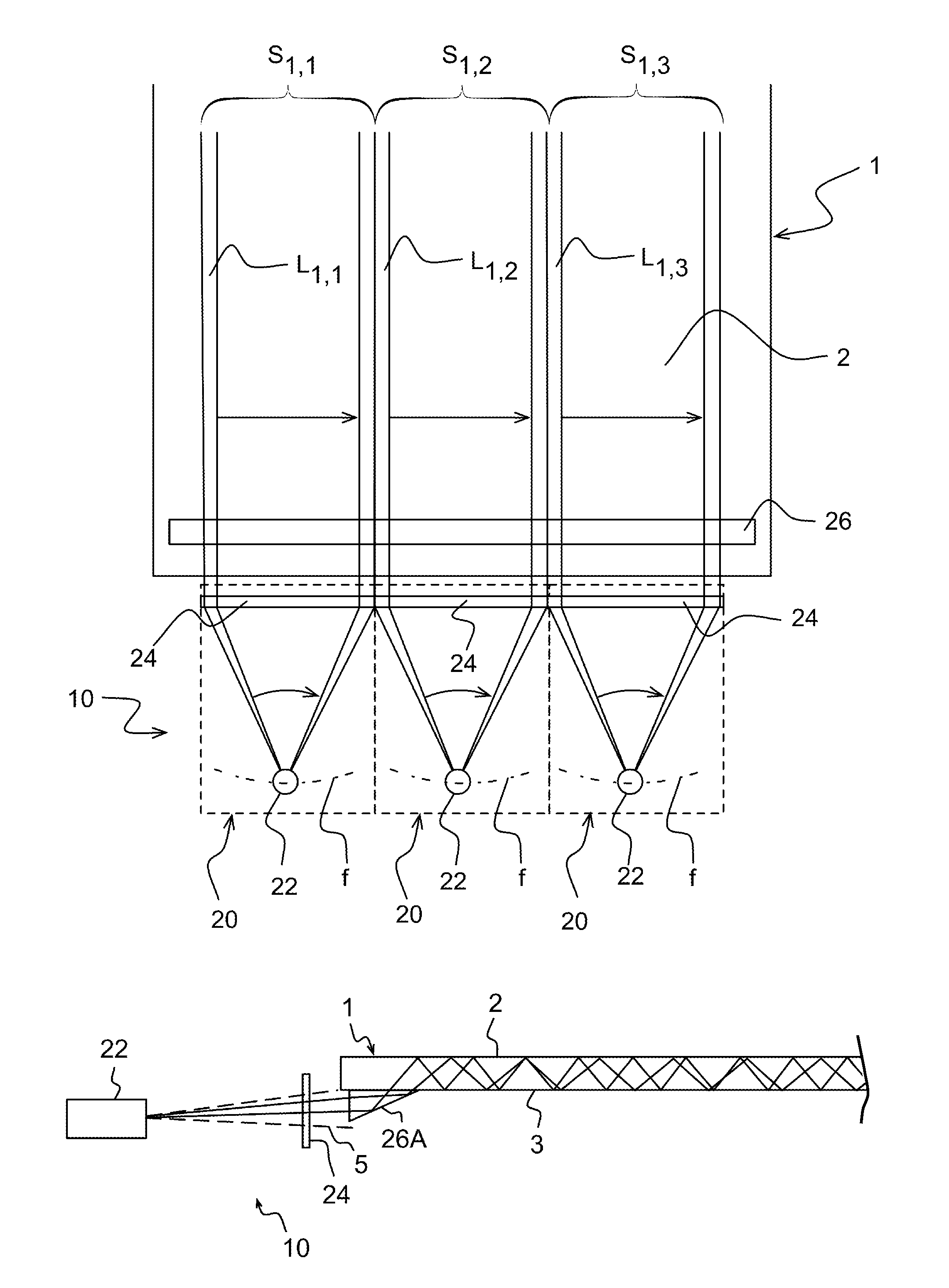
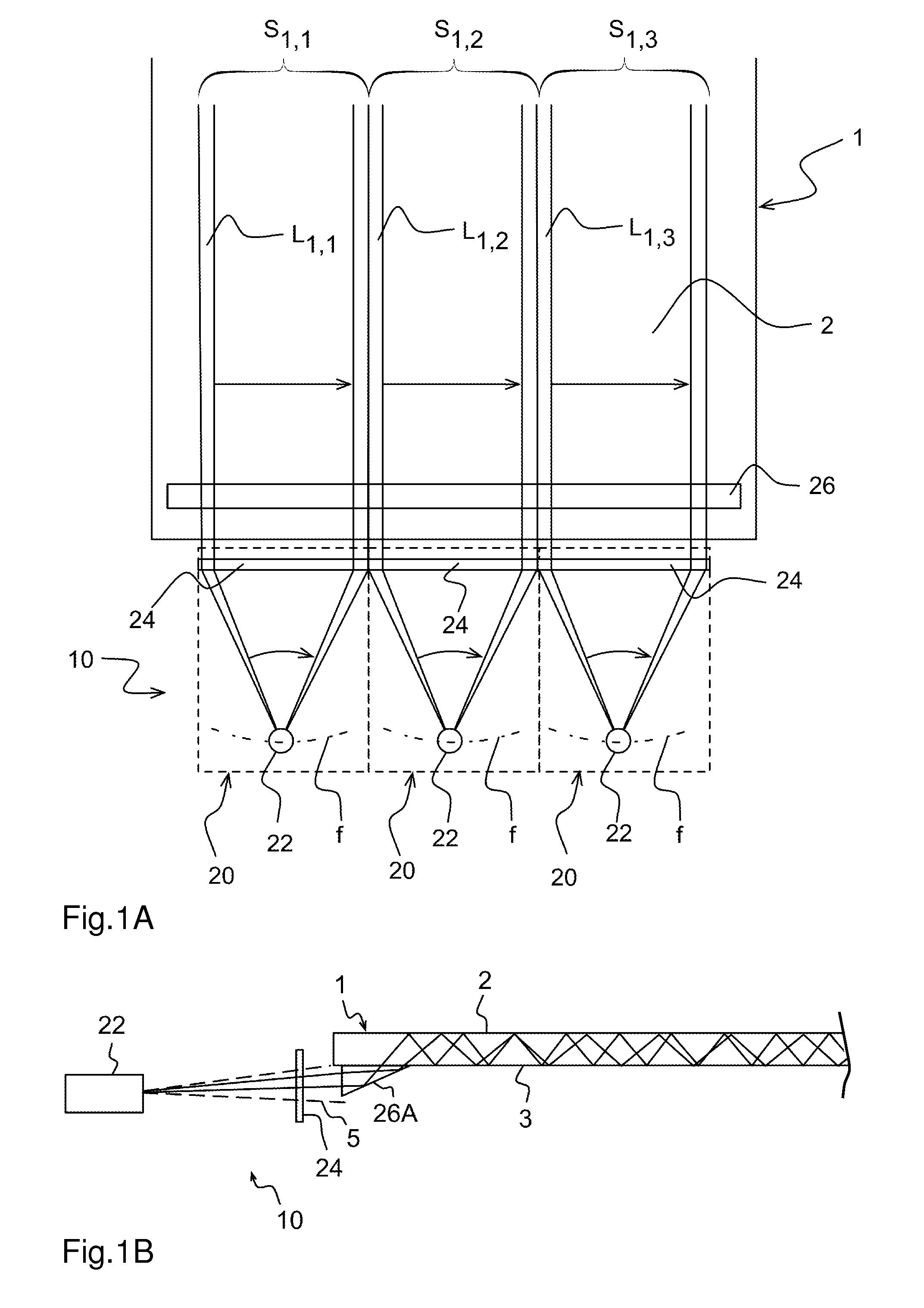
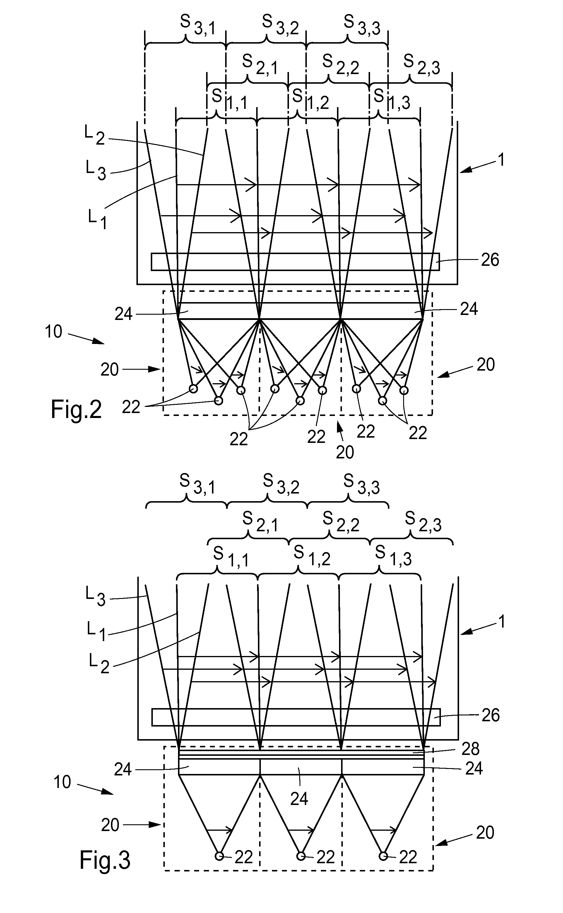
[0051]The present invention relates to a touch-sensitive apparatus that derives its touch sensitivity from light that propagates inside a transmissive panel while interacting with a touch surface of the panel. The interaction is formed when the propagating light is reflected by total internal reflection in the touch surface. When an object is brought into contact with the touch surface, the propagating light is disrupted (“frustrated”), causing an attenuation of the propagating light. By propagating light from different directions across the touch surface to form a grid of detection lines, and by measuring the energy of the received light for each detection line, the location of the object may be determined by processing the energy values for the detection lines.

[0052]The touch-sensitive apparatus thus utilizes the phenomenon of Frustrated Total Internal Reflection, FTIR. In the following; this type of touch-sensitive apparatus is denoted an “FTIR system”. FTIR systems have the pote...


PUM


Abstract

A touch-sensitive apparatus operates by FTIR (Frustrated Total Internal Reflection) to detect touches on a surface of a light transmissive panel. An illumination arrangement is controlled to propagate light by internal reflection from an elongated incoupling site on the panel to an elongated outcoupling site on the panel, and a detection arrangement is controlled to detect light reaching the outcoupling site. The illumination arrangement is controlled to sweep a first set of individual beams of light along different subsets of the incoupling site to generate a full beam sweep along the incoupling site. Thereby, the individual beams are be controlled to generate a “sub-sweep” of the incoupling site, which enables a compact design of the illumination arrangement and / or use of comparatively simple sweep generating devices and / or identical re-direction components in the illumination arrangement.

Description

CROSS-REFERENCE TO RELATED APPLICATIONS[0001]The present application claims the benefit of Swedish patent application No. 1051335-6, filed on Dec. 16, 2010, and U.S. provisional application No. 61 / 423,791, filed on Dec. 16, 2010, which are incorporated herein by reference.[0002]The invention is also related to U.S. provisional application No. 61 / 423,763, which was filed on Dec. 16, 2010 and is incorporated herein by reference.TECHNICAL FIELD[0003]The present invention relates to touch detection techniques, in particular optical detection of touching objects on a touch surface.BACKGROUND ART[0004]To an increasing extent, touch-sensitive panels are being used for providing input data to computers, electronic measurement and test equipment, gaming devices, etc. The panel may be provided with a graphical user interface (GUI) for a user to interact with using e.g. a pointer, stylus or one or more fingers. The GUI may be fixed or dynamic. A fixed GUI may e.g. be in the form of printed mat...

Claims


Application Information

Patent Timeline
Patent Type & Authority Patents(United States)
IPC IPC(8): G06M7/00G06F3/042
CPCG06F3/042G06F3/0423G06F2203/04109
Inventor BERGSTRÖM H{DOT OVER (A)}KANCRAVEN-BARTLE THOMAS
Owner FLATFROG LAB
Why Eureka
Try Eureka