Electric charge flow circuit for a time measurement

a technology of electric charge flow and time measurement, applied in the field of electronic circuits, can solve the problems of large dependence on the size of the leakage region, too thin elements, and insufficient thickness of dielectric layers, and achieve the effect of small leakage speed

Active Publication Date: 2014-10-28
STMICROELECTRONICS (ROUSSET) SAS
View PDF4 Cites 14 Cited by
  • Summary
  • Abstract
  • Description
  • Claims
  • Application Information

AI Technical Summary

Benefits of technology

[0012]Another embodiment provides a charge flow element of small leakage speed, which can be formed whatever the considered technological manufacturing process.

Problems solved by technology

A disadvantage is that, in practice, the sizing of the leakage region depends significantly on the considered technological manufacturing process.
In some recent technological processes, the dielectric layers available to form the leakage region of the flow element are too thin to enable the storage element to discharge slowly, even if the surface area of the leakage region is decreased to a minimum.
As a result, the time measurement can only be possible, in the absence of a power supply, for a very short time, poorly adapted to most applications.

Method used


Image

  • Electric charge flow circuit for a time measurement
  • Electric charge flow circuit for a time measurement
  • Electric charge flow circuit for a time measurement

Examples


Embodiment Construction

[0034]For clarity, the same elements have been designated with the same reference numerals in the different drawings and, further, as usual in the representation of integrated circuits, the various drawings are not to scale. Further, only those elements which are useful to the understanding of the embodiments have been shown and will be described. In particular, the destination of the time measurements generated by the described circuits has not been detailed, the described embodiments being compatible with usual applications of such time measurements.

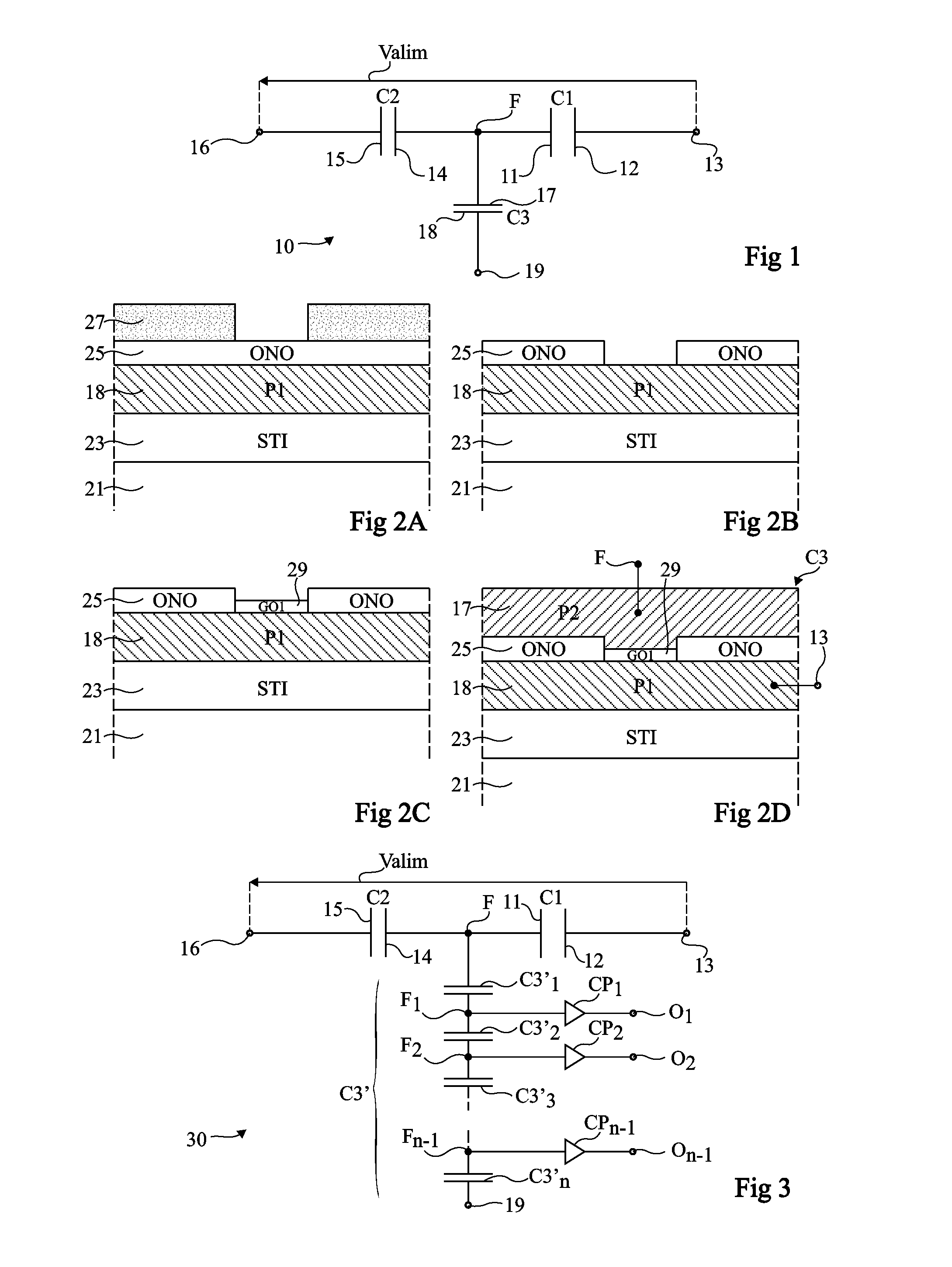
[0035]FIG. 1 is an electric diagram of an example of a circuit 10 capable of controllably retaining electric charges for a time measurement. Circuit 10 comprises a first capacitive element C1 having a first electrode 11 connected to a floating node F and having a second electrode 12 connected to a terminal 13 of application of a voltage, and a second capacitive element C2 having a first electrode 14 connected to node F and having a sec...


PUM


Abstract

A charge flow circuit for a time measurement, including a plurality of elementary capacitive elements electrically in series, each elementary capacitive element leaking through its dielectric space.

Description

CROSS REFERENCE TO RELATED APPLICATIONS[0001]This application claims the priority benefit of French patent application number 11 / 59025, filed on Oct. 6, 2011, which is hereby incorporated by reference to the maximum extent allowable by law.BACKGROUND[0002]1. Technical Field[0003]The present disclosure generally relates to electronic circuits, and more specifically the forming of a circuit enabling to controllably retain electric charges for a time measurement.[0004]2. Discussion of the Related Art[0005]In many applications, it is desired to have information representative of a time elapsed between two events, be it an accurate or approximate measurement. An example of application relates to the time management of rights of access, especially to media.[0006]The obtaining of this information representative of the elapsed time conventionally requires a time measurement by an electronic circuit powered, for example, by means of a battery, to avoid losing track of the information when th...

Claims


Application Information

Patent Timeline
Patent Type & Authority Patents(United States)
IPC IPC(8): H01L27/08H01L49/02H01L29/94H01L23/58H01L23/522G11C27/02G04F13/00H01L27/12H01L21/84
CPCH01L23/5223H01L29/94H01L27/1203G04F13/00H01L27/0805G11C27/024H01L21/84H01L28/40G01R27/2605G01R17/02G11C11/24H01G4/005H01G4/018H01G4/38H01L2924/0002G04F10/10H01L2924/00
Inventor LA ROSA, FRANCESCOFORNARA, PASCAL
Owner STMICROELECTRONICS (ROUSSET) SAS
Why Eureka
Try Eureka