Enhanced method of controlling the output of a hydroelectric turbine generator

a hydroelectric turbine and output technology, applied in the direction of engine fuction, active/predictive/anticipative control, engine control to cope with emergencies, etc., can solve the problems of not being economical to carry out regular maintenance on the various components, the installation and decommissioning of submarine turbine generators is relatively expensive, and the problem of significant challenges in harnessing tidal energy, etc., to achieve the reduction of the range of voltage variation, the effect of reducing the electrical stress acting on the power cabl

a hydroelectric turbine and output technology, applied in the direction of engine fuction, active/predictive/anticipative control, engine control to cope with emergencies, etc., can solve the problems of not being economical to carry out regular maintenance on the various components, the installation and decommissioning of submarine turbine generators is relatively expensive, and the problem of significant challenges in harnessing tidal energy, etc., to achieve the reduction of the range of voltage variation, the effect of reducing the electrical stress acting on the power cabl

US8872371B2Inactive Publication Date: 2014-10-28OPENHYDRO IP

Image

  • Enhanced method of controlling the output of a hydroelectric turbine generator
  • Enhanced method of controlling the output of a hydroelectric turbine generator
  • Enhanced method of controlling the output of a hydroelectric turbine generator

Examples


Embodiment Construction

[0049]An embodiment of the invention will now be described, by way of example only, with reference to the accompanying drawings, in which:

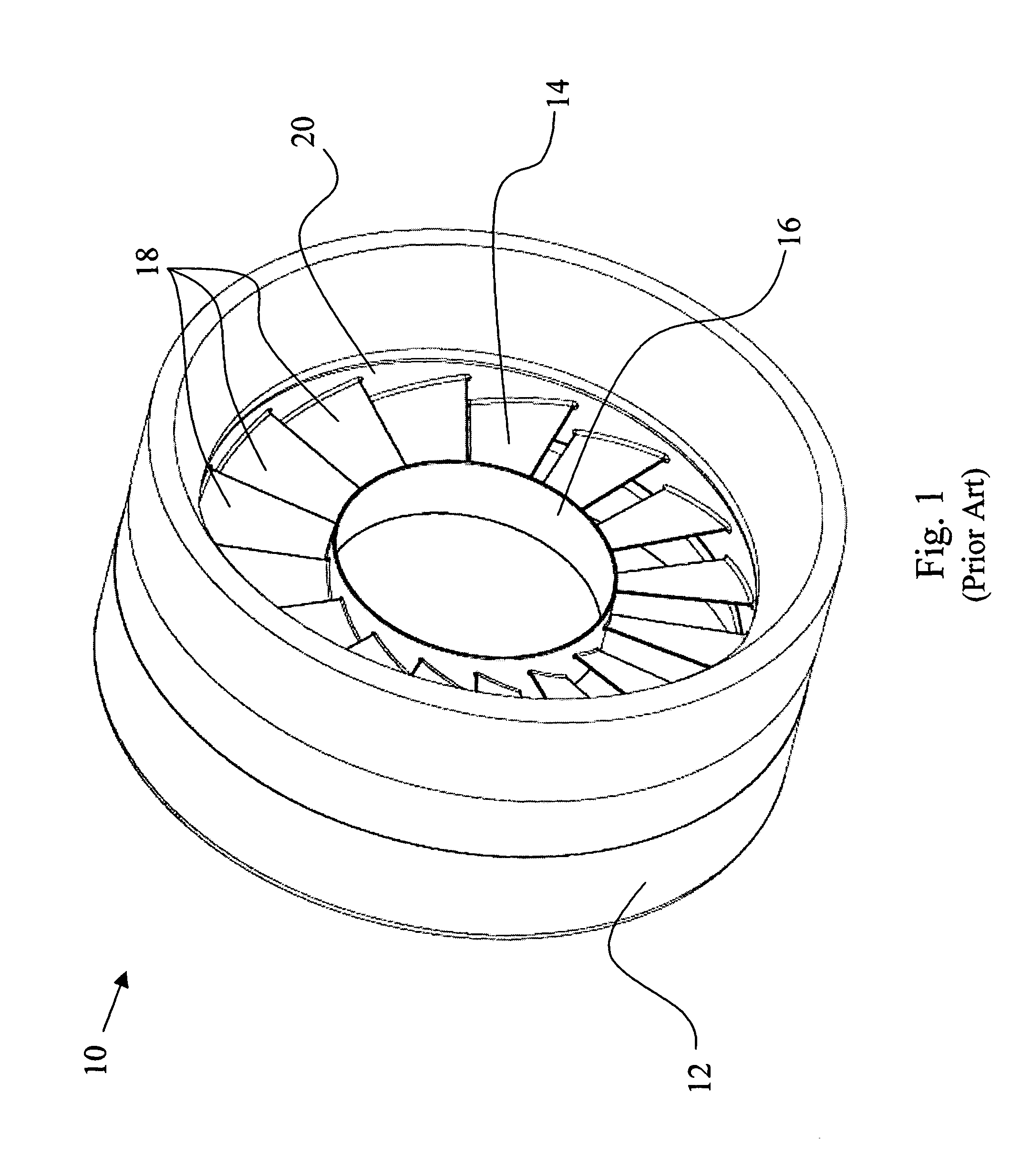
[0050]FIG. 1 shows a known tidal hydroelectric turbine generator;

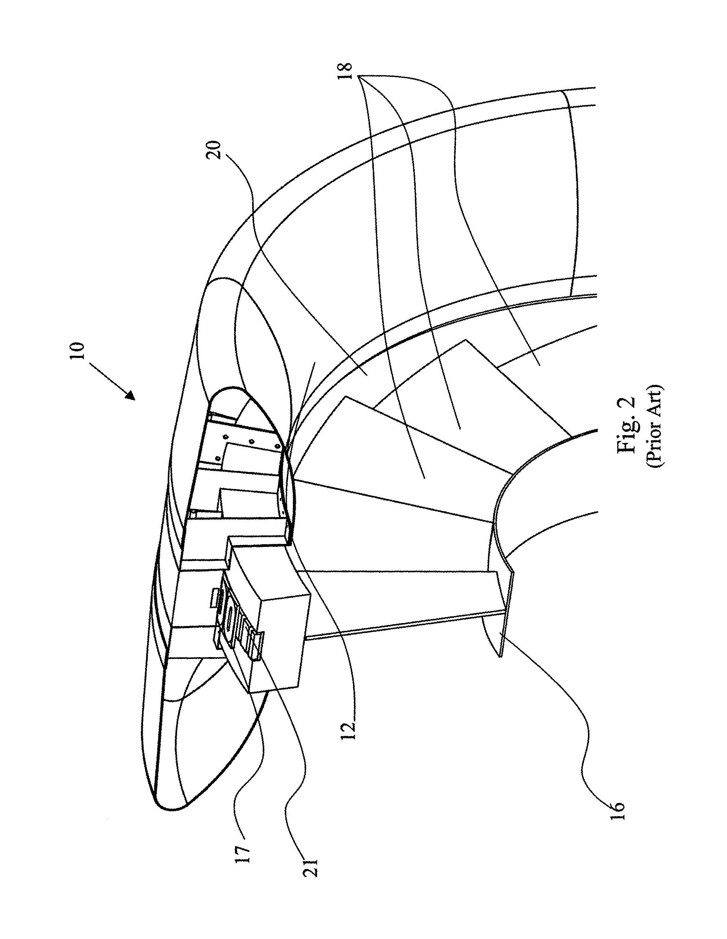
[0051]FIG. 2 shows a cross-section of a portion of the generator of FIG. 1;

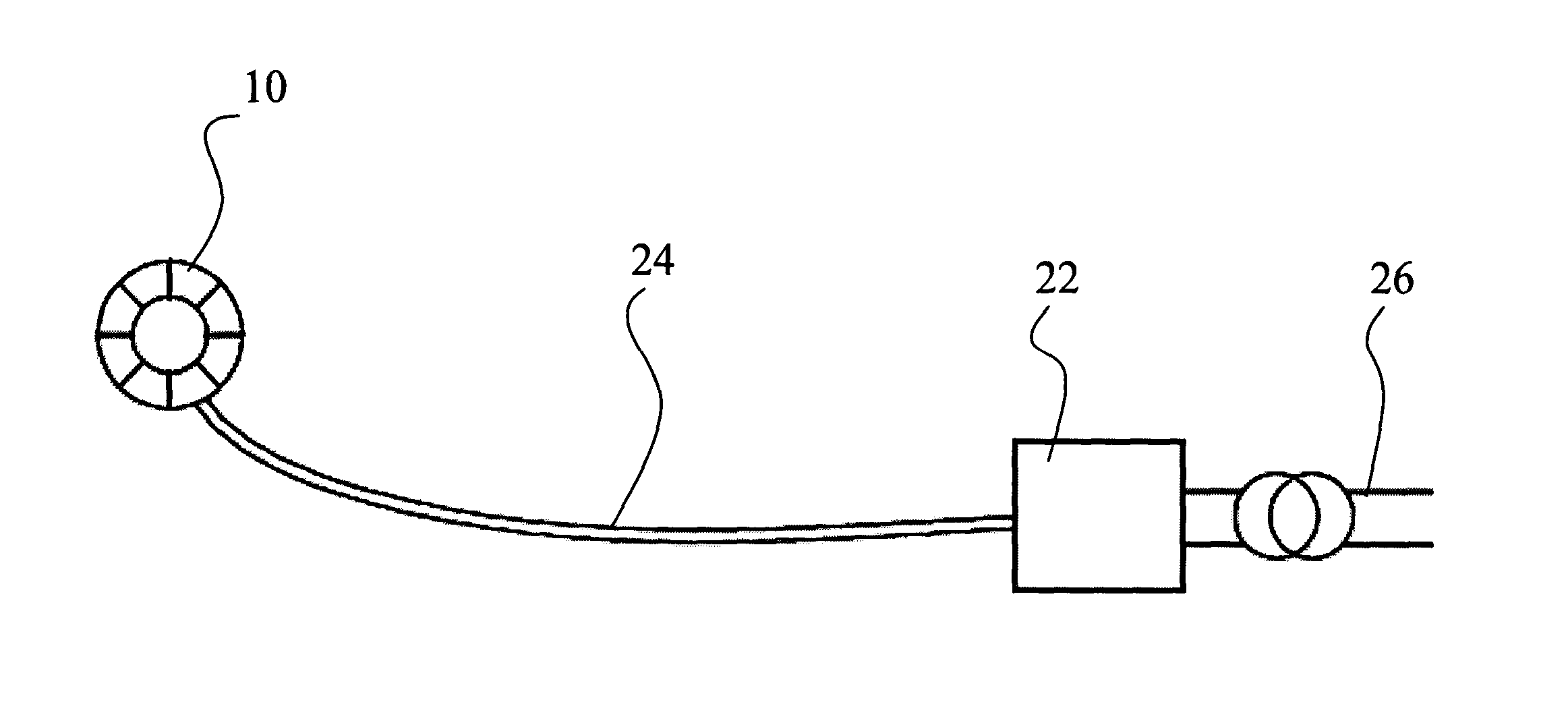
[0052]FIG. 3 shows the generator of FIG. 1 connected to an on-shore substation;

[0053]FIG. 4 is a graph of several torque speed curves for a sample turbine generator in different levels of tidal flow;

[0054]FIG. 5 is a graph of the voltage and current for a sample turbine generator;

[0055]FIG. 6 is an illustration of a sample control algorithm for the method of the invention;

[0056]FIG. 7 is a graph showing a sample variation of the transmission line voltage of a submarine power cable with respect to the speed of the tide;

[0057]FIG. 8 is a graph showing the optimum tip-speed for a turbine generator with respect to the speed of tidal flow at that turbine generator; and

[0058]FIG. 9 is a graph showing the line voltag...


PUM


Abstract

There is described a method for controlling the output of a tidal hydroelectric turbine generator from a remote location, with the need for control circuitry to be housed local to the generator. The rotational speed of the turbine, and consequently the output power level of the generator, is controlled by varying the transmission line voltage of the submarine power cable connecting the off-shore turbine with an on-shore substation.

Description

FIELD OF THE INVENTION[0001]The present invention relates to a method of controlling the output of a hydroelectric turbine generator, in particular controlling the output via the transmission system for that output, which additionally provides for the monitoring of fault conditions in the transmission system during periods of reduced generator output.BACKGROUND OF THE INVENTION[0002]The increased interest in environmental awareness, and a reluctance to rely on non-renewable sources of energy, has led to greater usage of renewable energy systems, e.g. solar power, wind power, thermal power, and tidal power. The latter involves the installation of turbine generators in an area of tidal flow, and converts the energy of the tides into electrical energy.[0003]With reference to FIGS. 1 and 2, an example hydroelectric turbine generator is described in PCT Application No. PCT / EP2007 / 006258. The generator 10 is of a direct-drive shaftless permanent magnet generator construction. The generato...

Claims


Application Information

Patent Timeline
28 Oct 2014
Publication
US8872371B2
IPC
F03B13/12; F03B15/00; F03B13/26; F03B13/10; H02P9/04
CPC
F05B2270/101; F05B2260/85; F03B15/00; F05B2270/404; F05B2270/107; F03B13/264; F05B2270/1033; Y02E10/28
Inventors
IVES, JAMES; TAAFFE, DAVID