Liquid crystal display device, multi-display device, method for determining light intensity, and storage medium

a display device and liquid crystal technology, applied in static indicating devices, cathode-ray tube indicators, instruments, etc., can solve the problems of unnaturally appearing images displayed, liquid crystal display devices which employ local dimming, etc., to reduce risks, increase average electric power consumption, and large brightness differences

Active Publication Date: 2014-10-28
SHARP KK
View PDF14 Cites 5 Cited by
  • Summary
  • Abstract
  • Description
  • Claims
  • Application Information

AI Technical Summary

Benefits of technology

[0019]With the configuration, it is possible to determine light intensities such that a difference of light intensities does not become too large (i) between adjacent segments in one (1) liquid crystal display device or (ii) between adjacent segments across adjacent liquid crystal display devices. In a case where, for example, (i) a first liquid crystal display device and a second liquid crystal display device are adjacent to each other and (ii) an object with high luminance is contained in an image which is indicated by peripheral display image data and is displayed on a display panel of the second liquid crystal display device, light intensities of respective segments of a backlight device included in the first liquid crystal display device can be determined such that a floating black level around the object with high luminance does not become conspicuous.
[0020]This makes it possible to reduce a risk that a large difference in brightness occurs (i) between adjacent areas in a display panel of one (1) liquid crystal display device or (ii) between adjacent areas across display panels of liquid crystal display devices adjacent to each other, even in a case where the adjacent areas, which face respective segments adjacent to each other, display respective partial images having identical or similar averages, etc. of luminance components. This prevents the multi-display device, in which the plurality of liquid crystal display devices are set in array, from displaying an image that appears unnatural.
[0021]According to the configuration, light can be emitted from only necessary segments. This allows suppression of an increase in average electric power consumption, as compared to a case where a background luminance is maintained by causing at least segments to emit light in the vicinity of panel border bezels as early described. Moreover, even in the vicinity of the panel border bezels, it is possible to cause (i) an area for displaying a bright image to be brighter and (ii) another area for displaying a dark image to be darker. It is therefore possible to display an image with a higher contrast ratio of bright and dark, as compared to the case where the background luminance in the vicinity of the panel border bezels is maintained.
[0022]Moreover, according to the configuration of the present invention, it is not necessary to maintain the background luminance by causing the segments to emit light in the vicinity of the panel border bezels, unlike the case where a background luminance is maintained by causing the segments to slightly emit light in the vicinity of the panel border bezels. With the configuration, electric power can be consumed by segments (whose number is smaller than that of the segments in the vicinity of the panel border bezels) for emitting light at maximum output, instead of being consumed for maintaining the background luminance. Therefore, in a case where a peak luminance increasing control is carried out for causing part of the segments to emit light with a luminance higher than that of light emitted by all the segments, it is possible to further heighten the peak luminance with the same electric power consumption as a case where such a peak luminance increasing control is carried out while maintaining the background luminance.

Problems solved by technology

However, the liquid crystal display device which employs local dimming has a disadvantage described below, in a case where, for example, one area displaying white and black images and another area displaying only a black image are adjacent to each other.
This leads to a difference in brightness of displayed black between one area and another area, resulting in an unnaturally-appearing image being displayed in which a boundary between the areas is conspicuous.

Method used


Image

  • Liquid crystal display device, multi-display device, method for determining light intensity, and storage medium
  • Liquid crystal display device, multi-display device, method for determining light intensity, and storage medium
  • Liquid crystal display device, multi-display device, method for determining light intensity, and storage medium

Examples


Embodiment Construction

[0039]The following description will discuss a configuration of a multi-display device of the present embodiment and processes carried out in the multi-display device, with reference to FIGS. 1 through 14.

[0040](Configurations of Liquid Crystal Display Device and Multi-display Device)

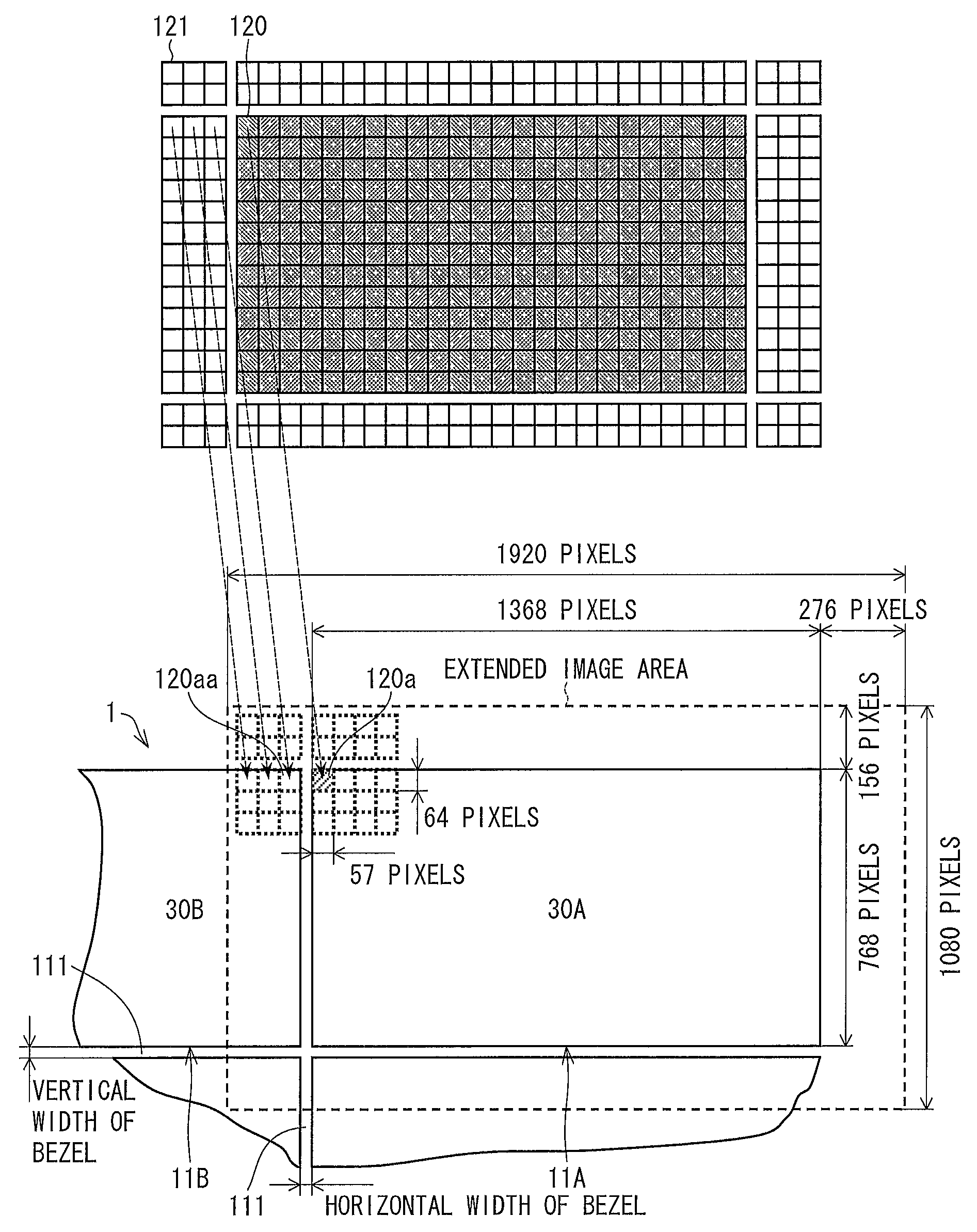
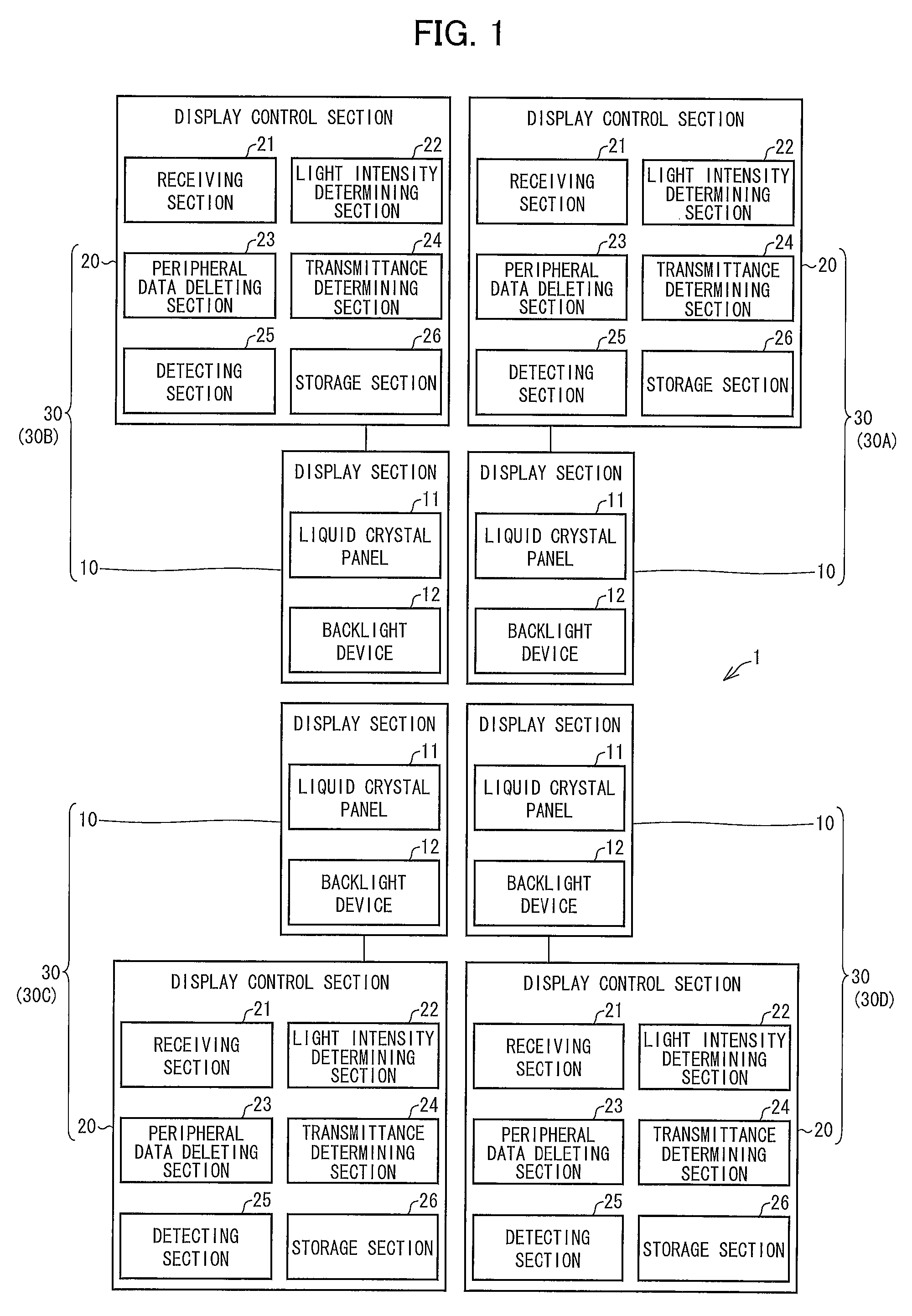
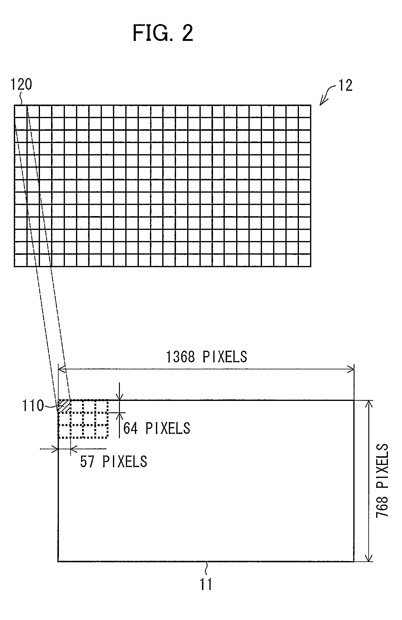
[0041]A multi-display device 1 of the present embodiment includes four liquid crystal display devices 30 (see FIG. 1). The four liquid crystal display devices 30 include respective liquid crystal panels 11, and the liquid crystal panels 11 are arranged in a matrix of 2×2 in the multi-display device 1. Note that the number of the liquid crystal display devices 30 is not limited to four, and therefore the present embodiment is suitably applicable to a multi-display device 1 including at least two liquid crystal display devices 30.

[0042]In the descriptions below, in a case where the four liquid crystal display devices 30 are distinguishingly referred to, symbols “30A”, “30B”, “30C”, and “30D” are given to ...


PUM


Abstract

The liquid crystal display device 30, included in the multi-display device 1, includes (i) a receiving section 21 for receiving display image data indicative of a display image to be displayed on a display panel 11 of the liquid crystal display device 30 and (ii) a light intensity determining section 22 for determining light intensity for each of segments of a backlight device 12 of the liquid crystal display device 30. When the receiving section 21 receives peripheral display image data, which is indicative of a peripheral image contiguous to the display image, the light intensity determining section 22 determines the light intensities of the respective segments based on the display image data and the peripheral display image data.

Description

[0001]This Nonprovisional application Claims priority under 35 U.S.C. §119 on Patent Application No. 2011-094535 filed in Japan on Apr. 20, 2011, the entire contents of which are hereby incorporated by reference.TECHNICAL FIELD[0002]The present invention relates to a liquid crystal display device and the like for use in a multi-display device, in which a plurality of liquid crystal display devices are adjacently arranged so as to display a large screen.BACKGROUND ART[0003]Conventionally, transmissive liquid crystal display devices are known as image display means. The transmissive liquid crystal display device is provided with a non-self-luminous liquid crystal panel and thus requires a backlight device. In such a backlight device, a cold cathode fluorescent lamp (CCFL) has been used as a light source. Recently, however, a backlight device including a LED as a light source is widely used, which is free from disadvantages of a cold cathode fluorescent lamp, such as environmental poll...

Claims


Application Information

Patent Timeline
Patent Type & Authority Patents(United States)
IPC IPC(8): G09G3/34G09G5/12
CPCG09G2360/16G09G2320/0646G09G2300/026G09G3/3426
Inventor YOSHIMURA, HIDEYOSHI
Owner SHARP KK
Why Eureka
Try Eureka