

Endoscope assembly with a polarizing filter
a technology of endoscope and filter, which is applied in the field of endoscope assembly with a polarizing filter, can solve the problems of endoscope camera, potential malignant (cancer) polyp to be missed, added discomfort, and complications for patients,
- Summary
- Abstract
- Description
- Claims
- Application Information
AI Technical Summary
Benefits of technology
Problems solved by technology
Method used
Image

Examples
Embodiment Construction
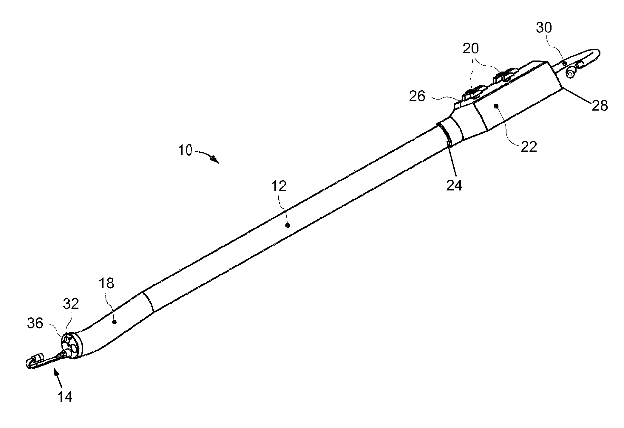
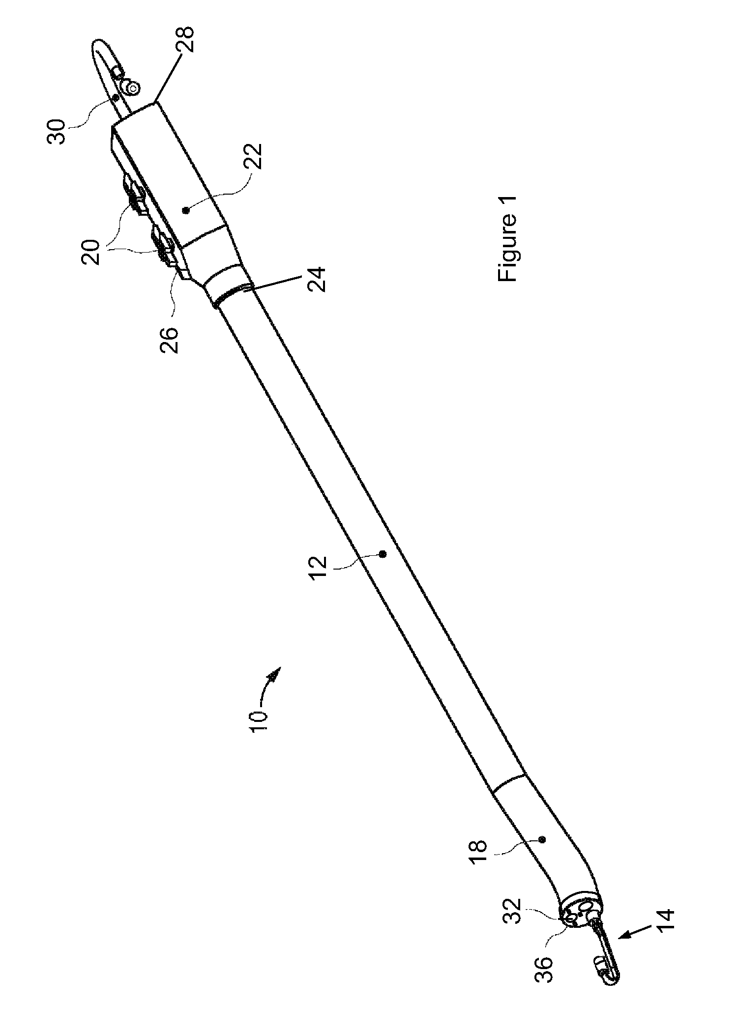
[0036]FIG. 1 illustrates a first exemplary endoscope 10 of the present invention. This endoscope 10 can be used in a variety of medical procedures in which imaging of a body tissue, organ, cavity or lumen is required. The types of procedures include, for example, anoscopy, arthroscopy, bronchoscopy, colonoscopy, cystoscopy, EGD, laparoscopy, and sigmoidoscopy.
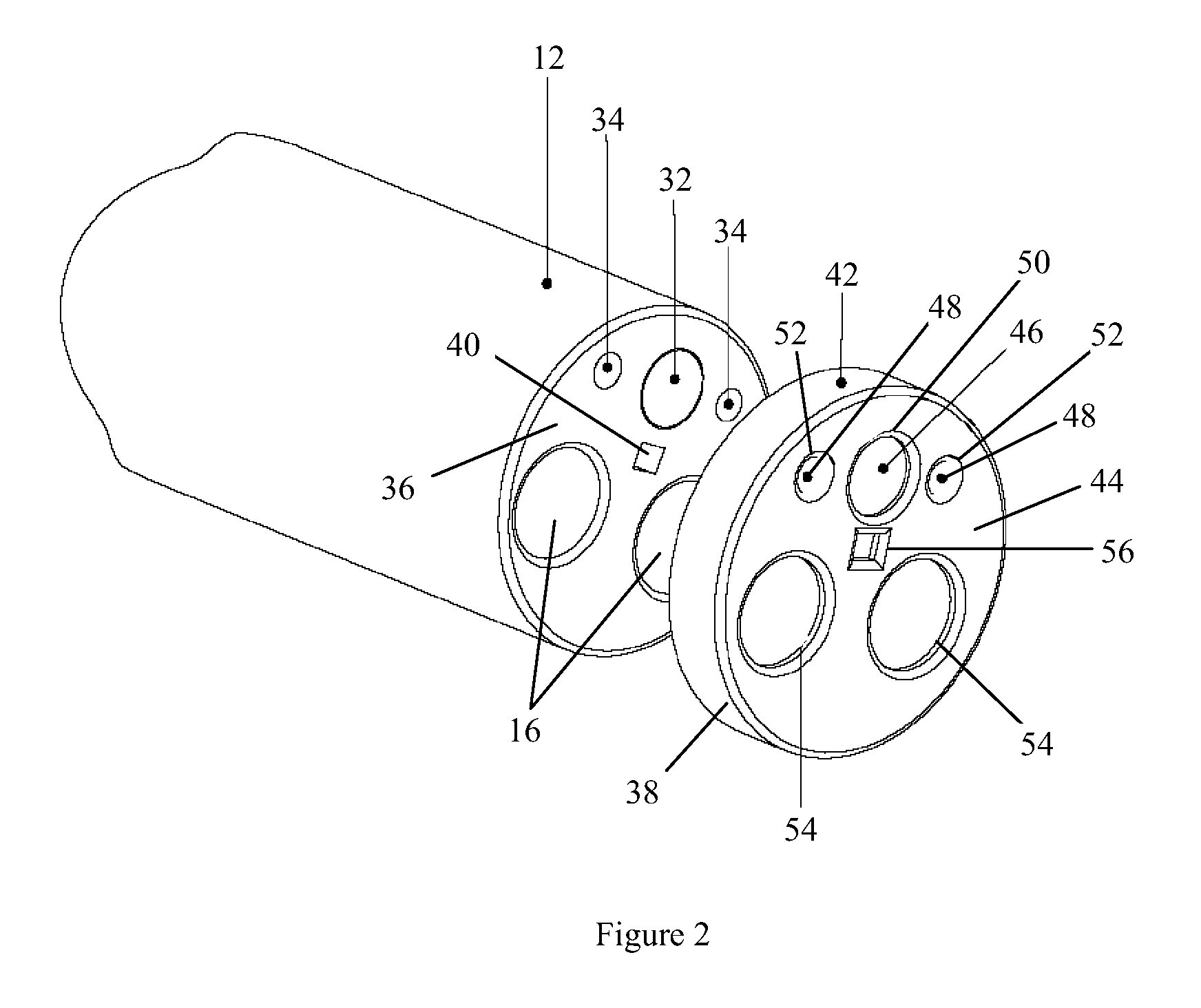
[0037]The endoscope 10 of FIG. 1 includes an insertion tube 12 and an imaging assembly 14, a section of which is housed inside the insertion tube 12. As shown in FIG. 2, the insertion tube 12 has two longitudinal channels 16. In general, however, the insertion tube 12 may have any number of longitudinal channels. An instrument can reach the body cavity to perform any desired procedures, such as to take samples of suspicious tissues or to perform other surgical procedures such as polypectomy. The instruments may be, for example, a retractable needle for drug injection, hydraulically actuated scissors, clamps, grasping tools, ele...
PUM
 Abstract
Description
Claims
Application Information