Apparatus and method for intraductal cytology

a technology of intraductal cytology and appendix, which is applied in the field of breast cancer detection, can solve the problems of surgery and radiation, up to 40% of breast cancer, and the failure of mammography to detect up to 20% of breast cancer in women over 50, and achieves the effect of convenient handling

Inactive Publication Date: 2005-01-11
LACHOWICZ THEODORE COLLATERAL AGENT
View PDF14 Cites 26 Cited by
  • Summary
  • Abstract
  • Description
  • Claims
  • Application Information

AI Technical Summary

Benefits of technology

[0027]It is also an object of the micro-endoscope assembly invention to c

Problems solved by technology

However mammography fails to detect up to 20% of breast cancers in women over 50 and up to 40% of breast cancers in younger women.
Surgery and radiation, of course, have risks and disadvantages well known to those of skill in the art.
Chemotherapy also can be particularly disadvantageous as, for example, when the drugs involved cause sickness to the patient when they enter the blood stream.
Unfortunately, most bioptomes are limited to large areas of entry and to taking a single tissue sample, after which the device must be withdrawn from the endoscope and the tissue collected before the device can be used again to take a second tissue sample.
Problems in the use of such an instrument include the small size required by the narrow small diameter lumens which can be blocked or limit the flow of fluid back through the aspiration lumen and thus preclude significant tissue collection or cause duct collapse.
While the '622 Patent shows a small lumen size the size problem is magnified with the other existing prior art if the same were to be applied to breast ducts and the endoscope is to be used with mammary duct inspection because of the small size and thin cell walls of the mammary ducts.
Thus almos

Method used


Image

  • Apparatus and method for intraductal cytology
  • Apparatus and method for intraductal cytology
  • Apparatus and method for intraductal cytology

Examples


Embodiment Construction

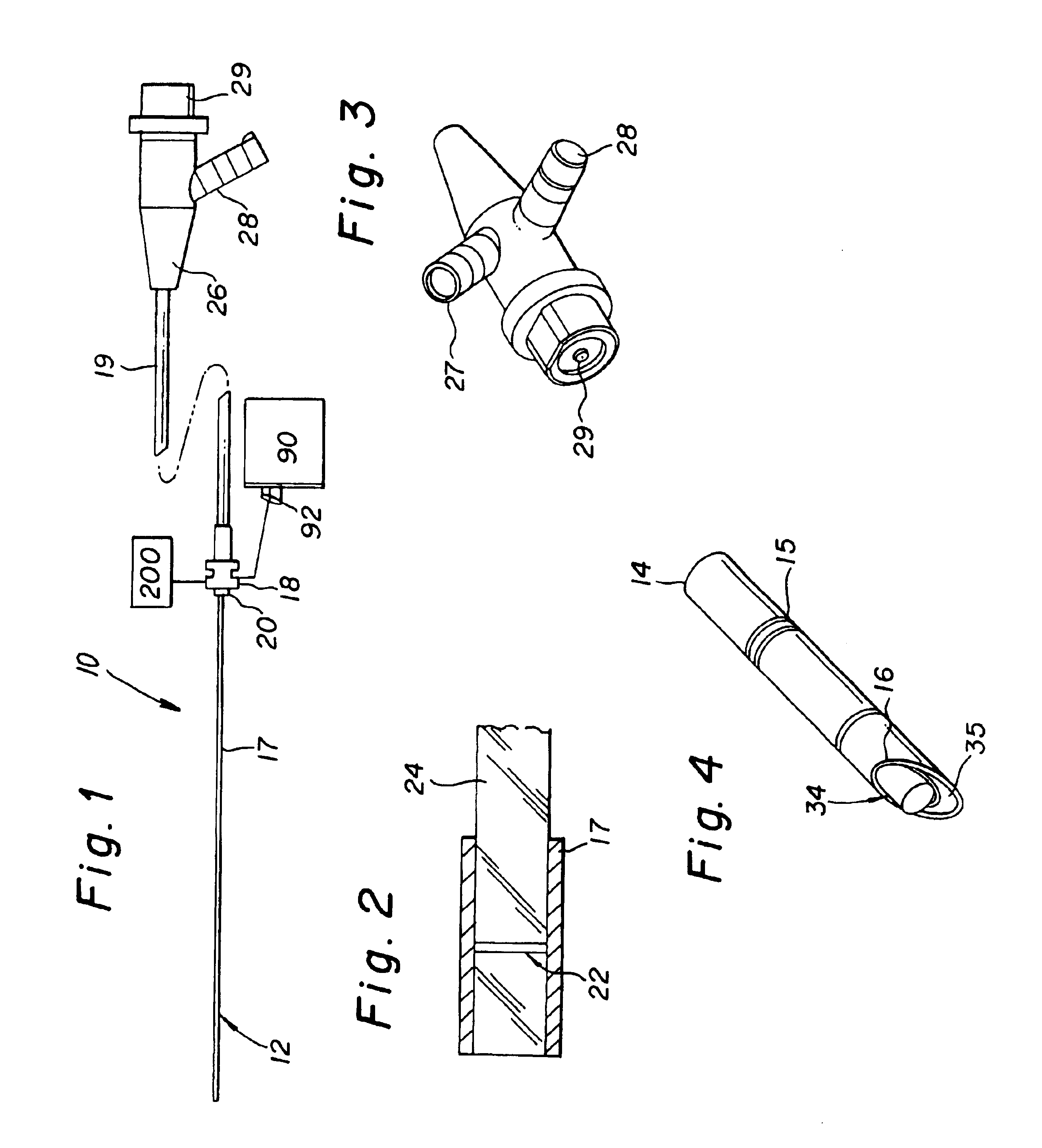
[0036]The present invention is directed towards a micro-endoscope assembly 10 which can be used and inserted into the lactiferous ducts of the breast of a woman patient and a method for intraductal cytology. The lactiferous ducts generally range in number from about six to about twelve in women and lead from areas of the breast to the nipple where they are in parallel vertical orientation with each other. The ducts have a very thin cell wall ranging from 3 to 4 cells in thickness and are resilient. The ducts have a smooth inner surface and white color which resemble visually the interior of a standard PVC pipe.

[0037]The best mode and preferred embodiment of the invention is shown in FIGS. 1-5. The micro assembly 10 consists of tube or guide cannula 14 which seats and guides the endoscope 12. The cannula 14 has an outer cylindrical wall 16 which defines an internal passageway which runs along its length to seat and guide the endoscope 12. Cannula tube 14 may be a rigid steel tube ran...


PUM


Abstract

The invention is directed toward a micro-endoscope assembly for the removal of tissue and cells from breast ducts comprising a cylindrical guide tube with a beveled distal end defining an internal cylindrical passageway and a first smaller cylindrical tube eccentrically formed in the cylindrical passageway of a smaller diameter than the tube internal cylindrical passageway and adapted to receive and guide an endoscope with a handle assembly wherein the smaller cylindrical tube together with an inner wall surface of the cylindrical guide tube forms a second passageway. A second conduit of a smaller diameter than the smaller cylindrical tube is mounted in the second passageway to divide the second passageway into two separate divided sections and is of sufficient diameter to receive a laser fiber and a micro-endoscope is mounted in the smaller cylindrical tube and a laser is mounted in the second cylindrical tube in the second passageway. The assembly is inserted into a mammary duct and the interior of the duct is viewed until an abnormality is determined in the duct. The tissue and cells from the abnormality area are dislodged, irrigated and aspirated through a suction channel to a removable collection device.

Description

RELATED APPLICATION[0002]There are no related applications.FIELD OF INVENTION[0003]The present invention is generally directed toward the detection of breast cancer and more specifically toward the detection and collection of cancer and / or abnormal growth tissue and cells in the mammary breast ducts of women.BACKGROUND OF THE INVENTION[0004]A leading disease incurred by women is breast cancer. Breast cancer is the second leading cause of death for women of all ages and the leading cause of death for women aged 25-55.Approximately one in eight women will incur breast cancer in their lifetimes. The current medical standard for determining breast cancer in women is mammography. However mammography fails to detect up to 20% of breast cancers in women over 50 and up to 40% of breast cancers in younger women. Breast cancer grows slowly but under current techniques such as mammography the average detection is only on cancer growths which have been growing over seven years at which time the...

Claims


Application Information

Patent Timeline
IPC IPC(8): A61B1/012A61B1/04A61B1/313A61B5/00A61B10/00A61B10/02A61B10/04A61B17/00A61B18/00A61B18/02A61B18/14A61B18/22
CPCA61B1/00135A61B1/012A61B1/0638A61B1/3132A61B5/0084A61B10/0041A61B10/02A61B10/04A61B18/1477A61B18/1815A61B2017/008A61B2017/32007A61B2018/00982A61B2018/0212A61B2018/0262A61B2018/1425A61B2018/1475A61B2018/1861A61B1/07A61B90/30A61B2090/306A61B2218/001
Inventor GATTO, DOMINICK L.
Owner LACHOWICZ THEODORE COLLATERAL AGENT
Why Eureka
Try Eureka