Surgical microscope support system

a support system and microscope technology, applied in the field of binocular microscope systems, can solve the problems of limited magnification factor of the device, inadequate loupe for a wide range of procedures, and essentially the entire weight of the system being carried by the operator's head

Inactive Publication Date: 2006-06-15
PIONTKOWSKI PAUL K
View PDF10 Cites 20 Cited by
  • Summary
  • Abstract
  • Description
  • Claims
  • Application Information

AI Technical Summary

Benefits of technology

[0020] Desirably, relevant movement between the operator's head and the scope assembly should be eliminated as much as possible. The scope should move and stop precisely with respective movement and stopping of the operator's head. In this way, the scope is always oriented along the operator's line of sight. The scope assembly plays an important role in this regard. The head harness must ensure that relative movement between the operator's head and the harness is prevented. Similarly, the mounting connection between the scope and the head harness should prevent relative movement between the two components. In a particular embodiment, the head harness comprises one or more adjustable strap members that encircle the operator's head. An additional strap member may be provided that passes over the operator's head. The strap configuration should be comfortable for the operator over an extended period of time while ensuring a tight and secure fit of the scope assembly to the operator's head. Any manner of adjustable mechanism, such as a buckle, hook and loop material, tightening knob, and so forth, may be used to tighten or loosen the straps on the operator's head.

Problems solved by technology

Although the loupe is relatively inexpensive and suffices for certain procedures, the magnification factor of the device is limited and the loupe is inadequate for a wide range of procedures.
A drawback, however, with the head mounted systems is that the overall weight of the system is borne essentially entirely by the operator's head.
This can be problematic, particularly during relatively long and intense procedures wherein any variable that adds to surgeon fatigue should be minimized.
These counterweights only add to the overall weight of the device.
The effort to overcome the inertia of the relatively heavy head mounted systems, and subsequent braking of the motion of the system at a desired position and angular orientation of the scope, is an unnatural exercise for the surgeon and can make the device difficult and frustrating to use.
This is particularly true at higher magnification powers wherein even a slight positional overshoot of the scope may result in a total loss of the relevant viewing field and a subsequent erratic “hunt-and-seek” effort to relocate the viewing field.
An inherent drawback of the externally stabilized suspended systems is that the procedure must be stopped in order to reposition the scope, particularly if this must be done by hand with handles provided on the optical heads.
Additionally, upon repositioning the scope, the overall weight of the scope and support structure results in a momentum that tends to carry the device beyond its desired position, often resulting in numerous and embarrassing attempts to correctly position the scope.
The power assist devices offer some improvement in this area, but are complicated, cost prohibitive for many practitioners, and do not offer total uninhibited range and motion of the scope.

Method used


Image

  • Surgical microscope support system
  • Surgical microscope support system
  • Surgical microscope support system

Examples


Embodiment Construction

[0030] Reference will now be made in detail to one or more embodiments of the invention, examples of which are graphically illustrated in the drawings. The embodiments are provided by way of explanation of the invention, and not meant as a limitation of the invention. For example, features illustrated or described as part of one embodiment may be utilized with another embodiment to yield still a further embodiment. It is intended that the present invention include these and other modifications and variations.

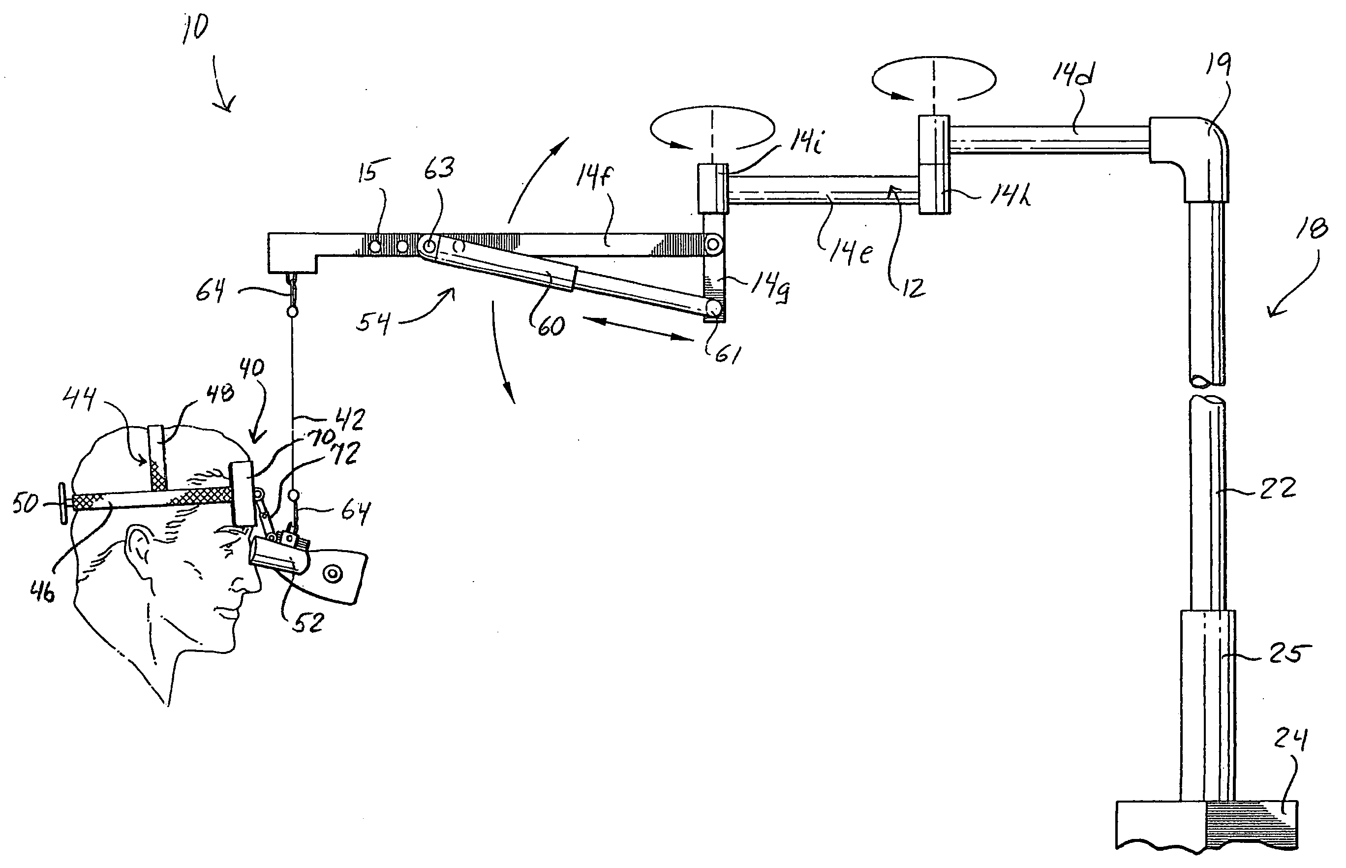
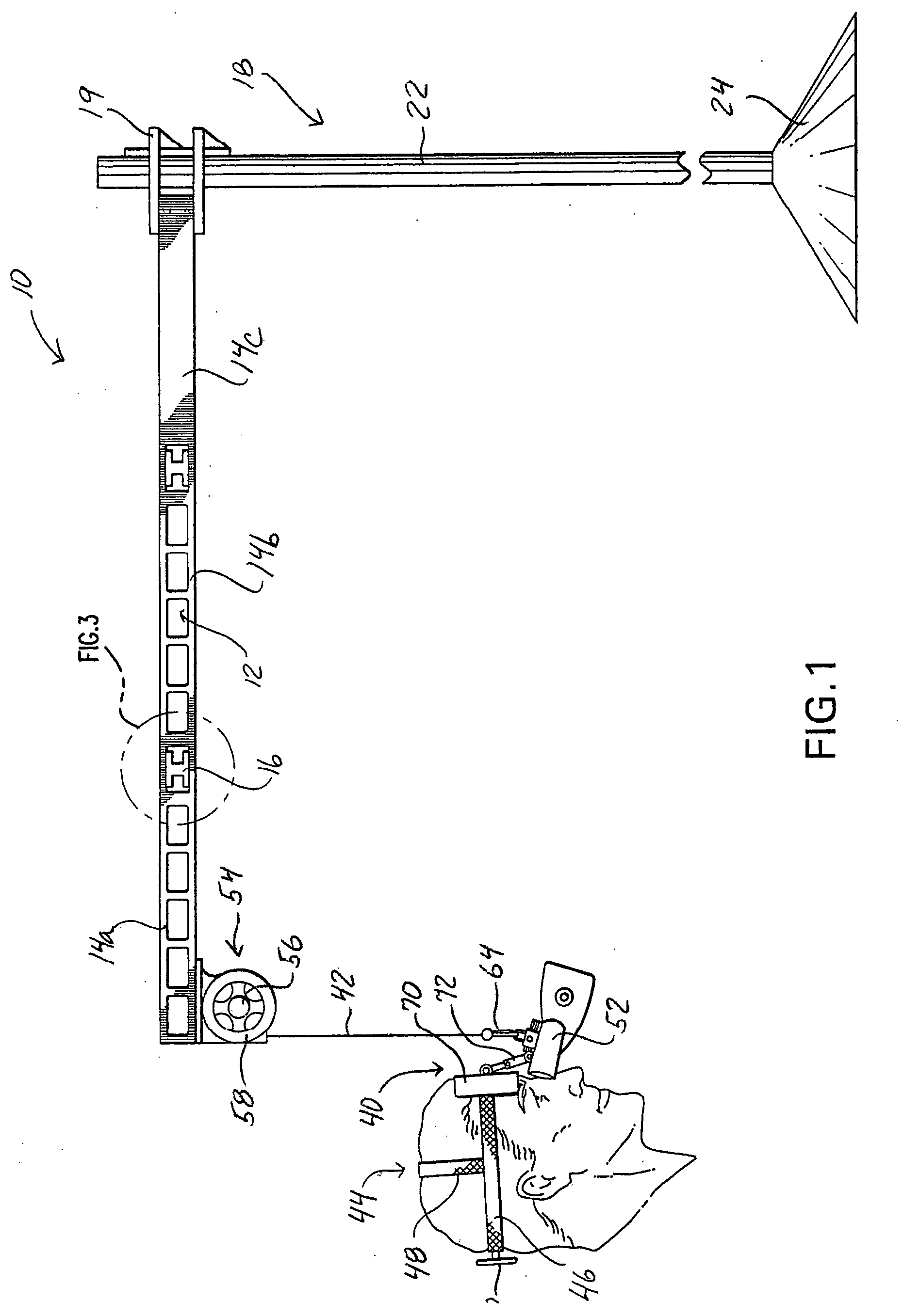
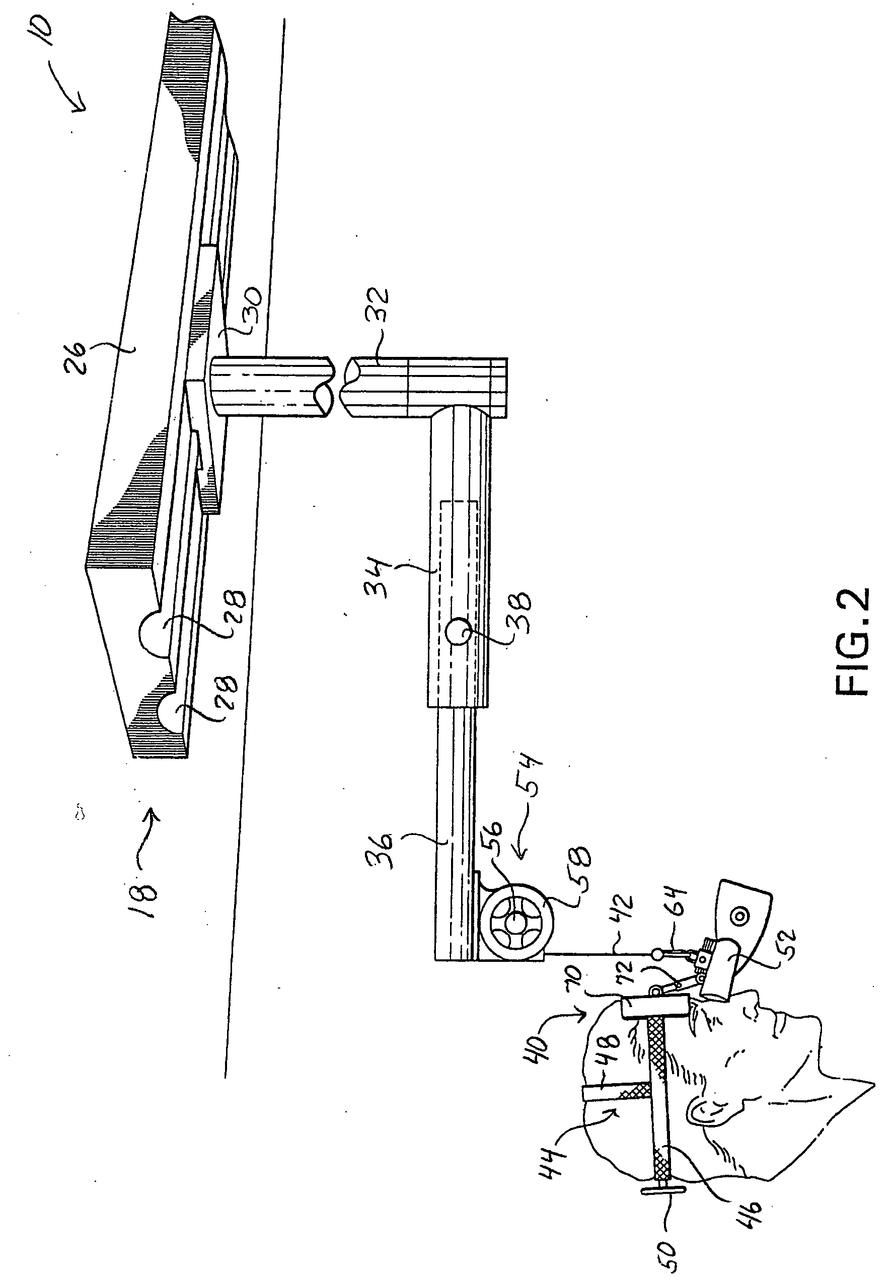
[0031] Various embodiments of a microscope system 10 according to the invention are illustrated in the figures. In the embodiment of FIG. 1, the microscope system 10 includes an adjustable arm 12 attached to a support mount 18. The mount 18 may take on various configurations. In the illustrated embodiment, mount 18 includes a vertically extending support pole 22 attached to a base unit 24. The base unit 24 may be stationary, wheeled, etc. Additionally, the support pole 22 may b...


PUM


Abstract

A microscope system includes an adjustable arm attached at one end to a support mount. A suspension member is configured at an opposite end of the adjustable arm and supports a scope assembly. The scope assembly includes a head harness and a microscope adjustably connected to the harness such that the microscope is disposed along an operator's line of site upon the operator donning the head harness. A weight compensator device is configured on the arm to compensate for the weight of the scope assembly hanging on the suspension member.

Description

PRIORITY CLAIM [0001] The present application claims priority to U.S. Provisional patent application Ser. No. ______ filed on Dec. 14, 2004. RELATED APPLICATIONS [0002] The present application is related in subject matter to the co-pending U.S. application Ser. Nos. 10 / 320,385 filed on Dec. 17, 2002, and Ser. No. 10 / 646,929 filed on Aug. 25, 2003, from the same inventor. The '385 and '929 applications are incorporated herein in their entirety for all purposes.FIELD OF THE INVENTION [0003] The present invention relates to the field of binocular microscope systems used, for example, in various surgical procedures, and more particularly to an improved support system for a binocular microscope. BACKGROUND [0004] The need for magnification of a surgical or medical procedure site is widely recognized in the medical arts, and a number of devices are available for this purpose. The most common device is the loupe (or pair of loupes), which is essentially a lens mounted to an eyeglass frame....

Claims


Application Information

Patent Timeline
Patent Type & Authority Applications(United States)
IPC IPC(8): B26B21/00
CPCA61B19/26A61B19/5223A61B2019/262A61B2019/263F16M11/04F16M11/10F16M11/12F16M11/18F16M11/2064F16M13/02F16M13/04F16M2200/044G02B7/001A61B90/20A61B90/50A61B2090/502A61B2090/5025
Inventor PIONTKOWSKI, PAUL K.
Owner PIONTKOWSKI PAUL K
Why Eureka
Try Eureka