Insulated pipe coupling

a technology of insulated pipes and couplings, applied in the field of couplings, can solve problems such as hydrate formation in equipment, blockage of flow through tubing, damage to equipment, etc., and achieve the effect of preventing hydrate formation

Active Publication Date: 2014-11-04
FMC KONGSBERG SUS
View PDF18 Cites 6 Cited by
  • Summary
  • Abstract
  • Description
  • Claims
  • Application Information

AI Technical Summary

Benefits of technology

[0017]The pipe coupling apparatus comprises at least one insulating element, but in one embodiment comprises a plurality of insulating elements which may have the same or different form and extent, for example, a first, second and / or third insulating element. The insulating elements will be configured and arranged to the pipe flanges in such manner that, in addition to preventing hydrate formation, they will also protect the pipe coupling from impacts, knocks or loads to which the coupling is subjected during installation and use, and so that they will be able to take up forces and / or loads to which the pipe coupling is subjected during coupling and uncoupling.
[0018]These insulating elements may be arranged and connected to each of the pipe flanges. If one or both of the pipe flanges is connected to, for example, a pipe, an additional longitudinal insulating element can be arranged around the pipe and connected to the insulating element that is connected to the pipe flange, the elongate insulating element thereby extending over a length of the pipe. The insulating elements that are connected to the pipe flanges are, on the sides facing each other, further configured with complementary faces. When the pipe flanges are coupled together, the insulating elements will form a “continuous” element that will seal against heat loss through convection.

Problems solved by technology

In addition to the above loads, the deployed equipment, because of the depth or the waters in which it is deployed, will be exposed to seawater that is just a couple of degrees above freezing point.
If the well, for example, is choked or closed off temporarily, the hydrocarbons that are in the tubing will be cooled to temperatures as low as the temperatures of the water, which may lead to hydrate formation in the equipment.
This can result in the flow through the tubing being blocked or in the equipment being damaged.

Method used


Image

  • Insulated pipe coupling
  • Insulated pipe coupling
  • Insulated pipe coupling

Examples


Embodiment Construction

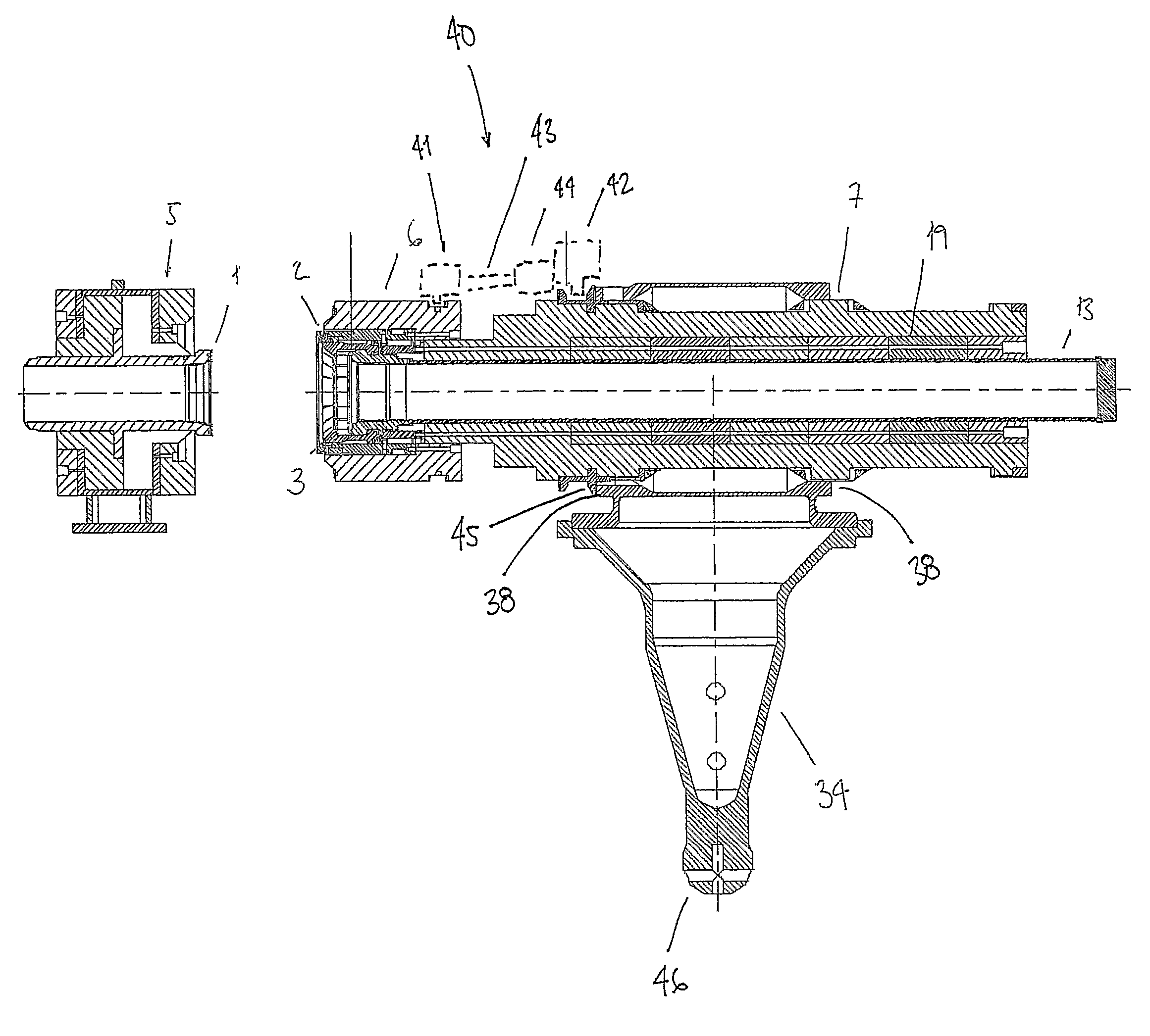
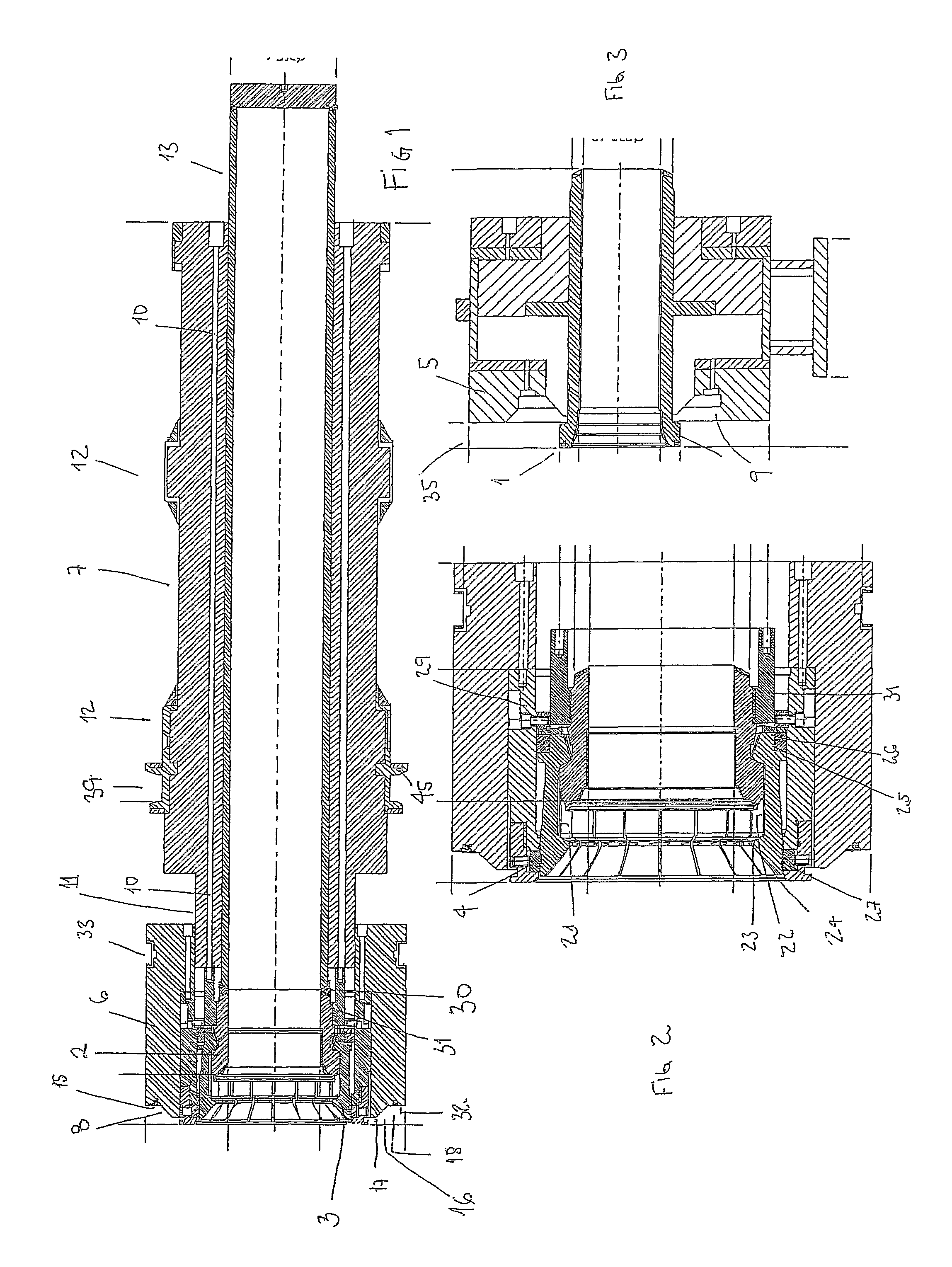
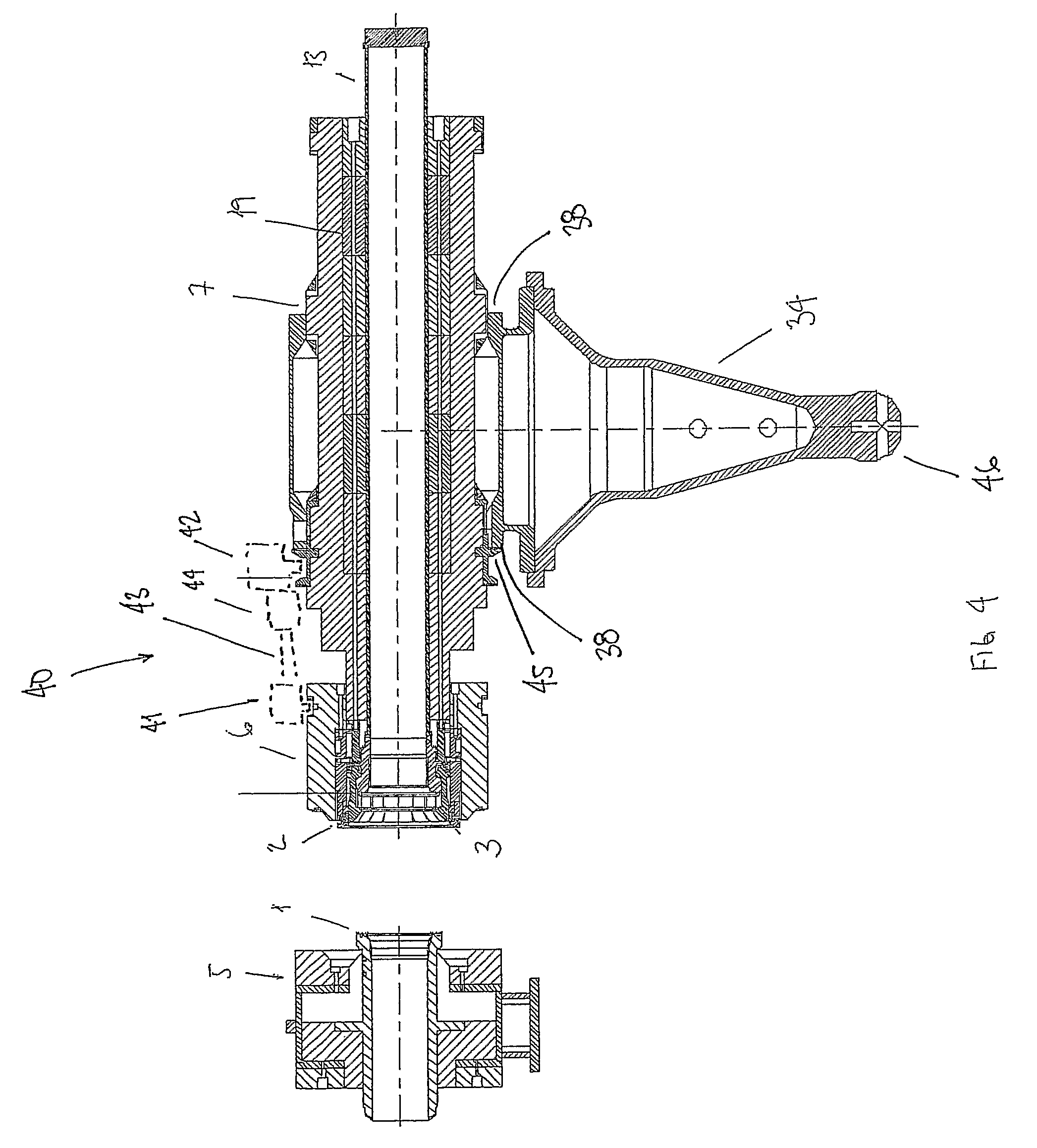
[0033]FIGS. 1 and 2 show a termination head which constitutes an end termination for a pipeline, umbilical, cable or the like that is provided to be connected to a stationary structure on the seabed. It comprises a pipe flange 2 which via a weld 30 is connected to a pipe 13. One or more gripping elements 3 are arranged on the pipe flange 2, which gripping elements 3 may, for example, be fingers that are arranged around the periphery of the second pipe flange 2. The fingers run parallel to the axial direction of the pipe 13.

[0034]The fingers 3 are arranged loosely around the periphery of the second pipe flange 2, but are held in their positions by surrounding elements. In addition, non-illustrated guides, which may, for example, be pins in the fingers, will ensure that the fingers do not twist about radial axes.

[0035]To obtain a locking on the coupling together of two opposing pipe flanges 1, 2, the fingers 3, on one side that is to rest against a first pipe flange 1 (shown in FIG. 2...


PUM

PropertyMeasurementUnit
insulatingaaaaaaaaaa
diameteraaaaaaaaaa
force-transmitting propertiesaaaaaaaaaa

Abstract

A pipe coupling apparatus for coupling together first and second opposing pipe flanges includes a number of gripping elements which are connected to the second pipe flange and are engageable with the first pipe flange. A locking element is displaceably arranged on the second pipe flange to lock the gripping elements to the first pipe flange when the pipe flanges are coupled together, and an insulating element extends around the second pipe flange and is connected to the locking element. The apparatus includes an actuating tool for displacing the first insulating element and thus the locking element.

Description

BACKGROUND OF THE INVENTION[0001]The present invention relates to a coupling that is insulated and that is used to couple together two opposing (pipe) flanges, which insulated pipe coupling comprises gripping and retaining elements for locking and securing the flanges when they are coupled together, wherein the insulating elements are connected to the flanges. Furthermore, the invention also relates to a pipe coupling apparatus comprising two pipe flanges and at least one pipe, as well as means for coupling together the two pipe flanges, wherein at least one of the pipe flanges is connected to a pipe.[0002]In connection with different types of operations that are carried out during the offshore production of hydrocarbons, it will be necessary, for various reasons, to be able to connect and disconnect the equipment used. This may, for example, be the case for different equipment that is placed on the seabed, where components such as manifolds, pumps, pressure tanks etc. are connected...

Claims


Application Information

Patent Timeline
Patent Type & Authority Patents(United States)
IPC IPC(8): F16L59/18F16L1/26B23P19/04
CPCF16L59/188F16L1/26Y10T29/53678Y10T29/5367
Inventor BEKKEVOLD, KNUT, HAVARD
Owner FMC KONGSBERG SUS
Why Eureka
Try Eureka