
Method to produce natural gas liquids (ngl's) at gas pressure reduction stations

a technology of gas pressure reduction and natural gas liquid, which is applied in the direction of gaseous fuels, fuels, and petroleum industry, can solve the problems of not being able to recover the ngls present in the natural gas stream at metering and pressure reduction, and achieve the effects of preventing the formation of hydrates, reducing temperature, and recovering most of energy

Active Publication Date: 2009-11-19
1304338 ALBERTA
View PDF8 Cites 7 Cited by
  • Summary
  • Abstract
  • Description
  • Claims
  • Application Information

AI Technical Summary

Benefits of technology

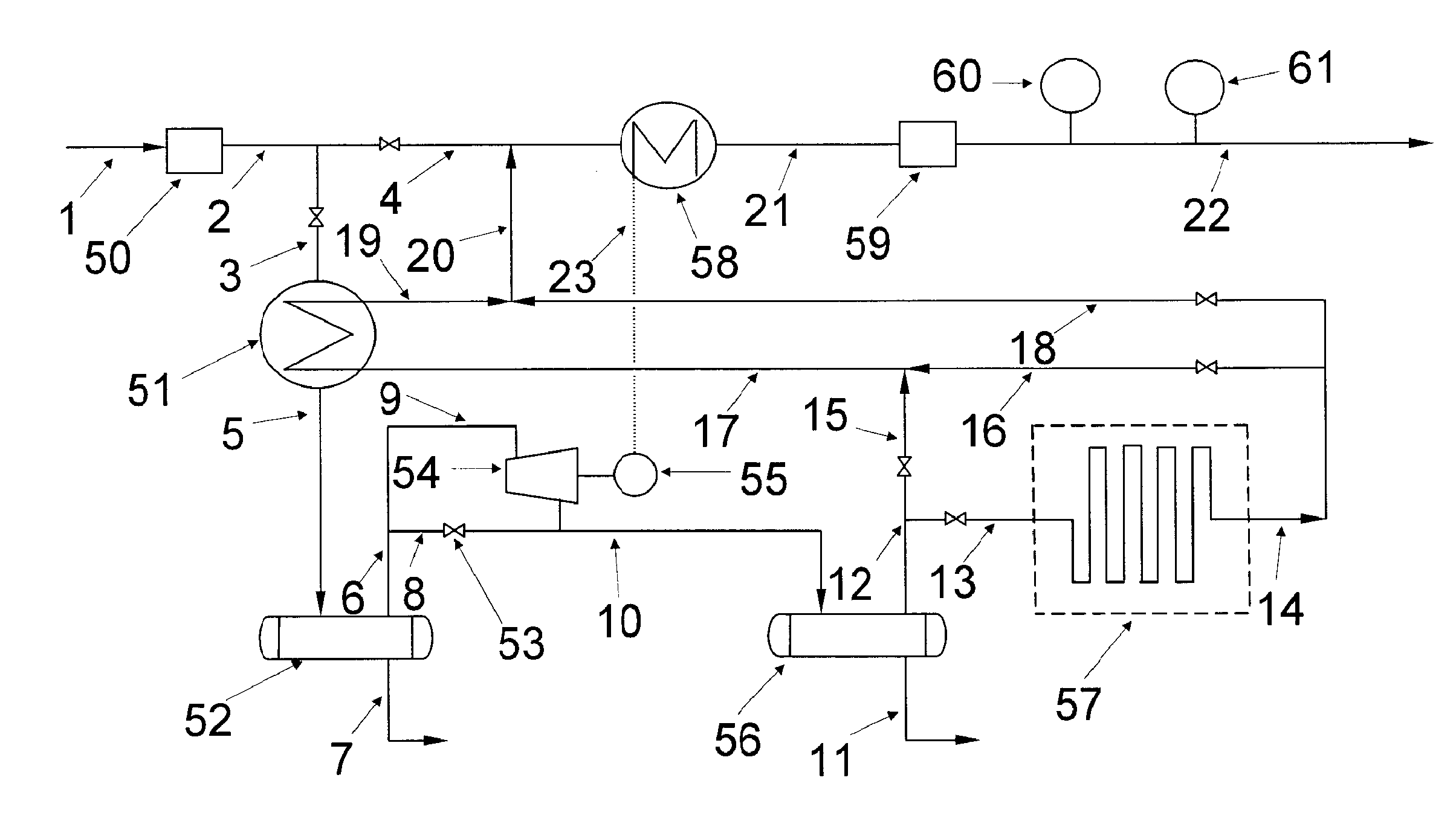
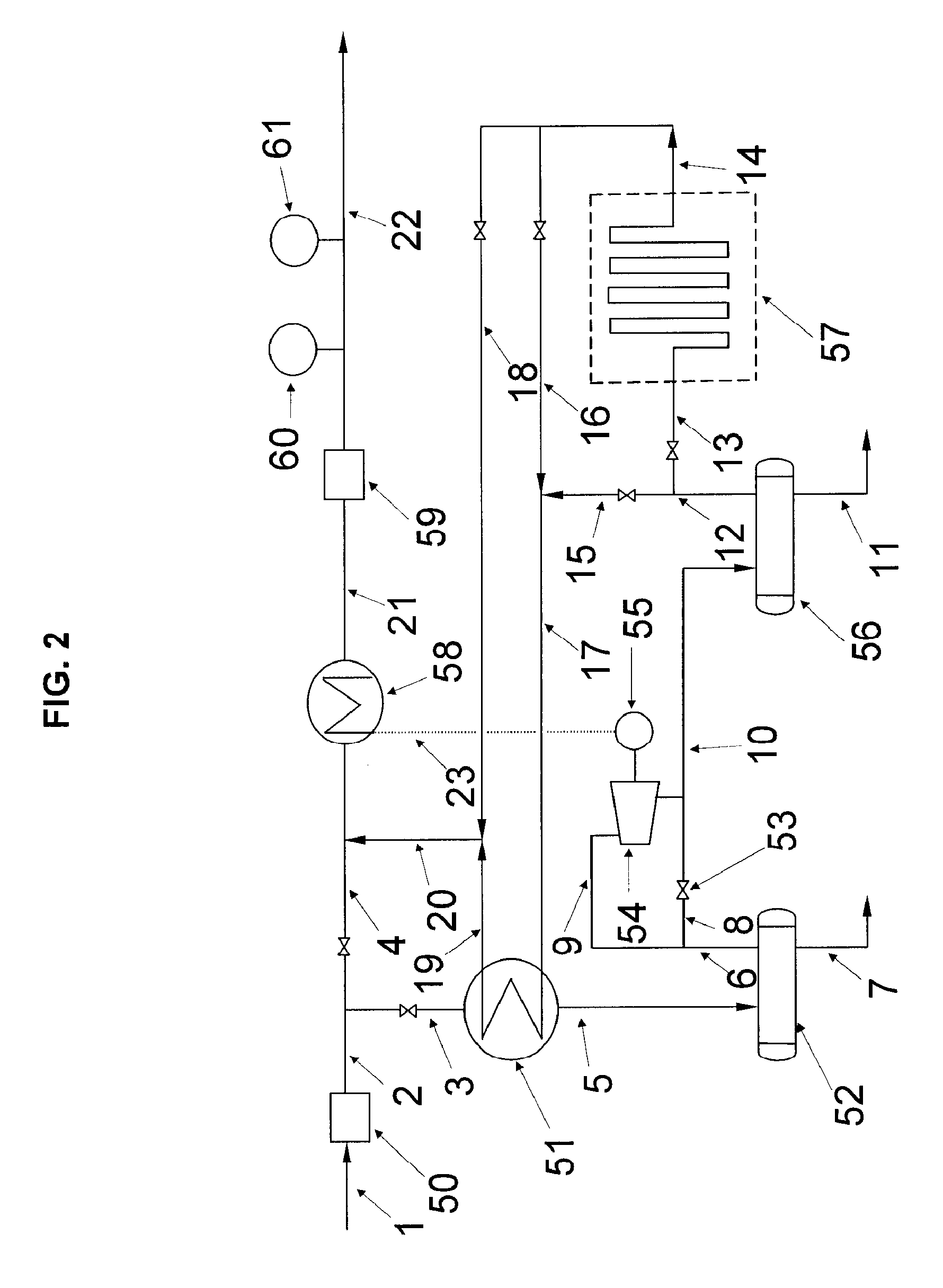
[0003]According to the present invention there is provided a method to remove water present in the gas stream, produce NGL's and then pre-heat the gas to meet pipeline specifications. This method recovers NGL's, removes water and eliminates the present practice of using natural gas as a fuel for; boilers, heaters, gas turbines, gas engines or fuel cells to pre-heat the natural gas before pressure reduction. Moreover, the present invention provides the ability to recover most of the energy available for recovery at pressure reduction stations. A first step has at least one heat exchanger, with a first flow path for passage of incoming high pressure gas that indirectly exchanges heat with a counter current lower pressure cold gas stream. The low pressure cold gas stream flow can be controlled to meet desired temperatures in the high pressure gas stream through the use of a by-pass around the heat exchanger. The now cold high pressure gas enters a vessel separator, where water is removed. A second step involves passing the high pressure cold and water free gas stream through a gas expander, dropping the pressure to local distribution pipeline spec generating shaft work and a further drop in temperature. The shaft rotates a power generator producing electricity and the lower pressure colder gas enters a separator where NGL's are recovered. The objective being to control the temperature upstream of the gas expander to meet the desired NGL's recovery. The third step involves the use of the generated electricity as an heat source to the heat exchanger that controls the gas supply temperature to the local distribution pipeline. This eliminates the existing practice of combusting natural gas to pre-heat the gas to prevent the formation of hydrates. The fourth step involves the use of air exchangers to release part or all of the cold energy to the surroundings, this provides the ability to export electricity at warm atmospheric conditions.

Problems solved by technology

The limitation in these applications are the economics which are driven by flow volumes, pressure delta, seasonal volumetric flows and 24 hour volumetric flows.
In all of the above practices, there is no attempt made to recover NGL's present in the natural gas stream at Metering and Pressure Reduction Stations.

Method used


Image

  • Method to produce natural gas liquids (ngl's) at gas pressure reduction stations
  • Method to produce natural gas liquids (ngl's) at gas pressure reduction stations
  • Method to produce natural gas liquids (ngl's) at gas pressure reduction stations

Examples


Embodiment Construction

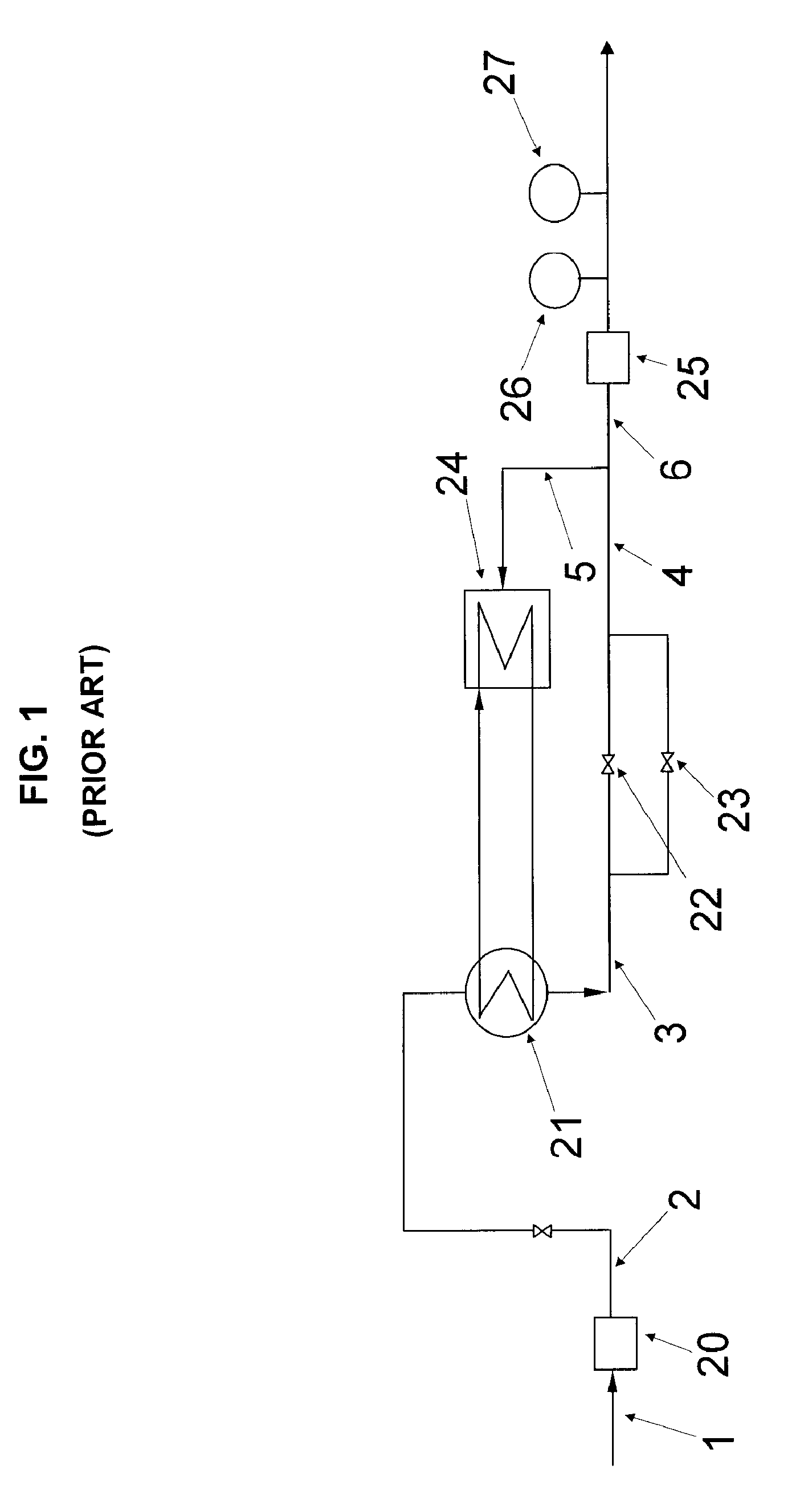
[0010]The typical method that presently is used to pre-heat natural gas at Pressure Reduction Stations will now be described with reference to FIG. 1.

[0011]In this typical gas pre-heating process, gas enters a station via gas supply line 1. The gas stream enters filter 20 to remove any debris in the stream. The filtered gas exits the filter through line 2 and enters heat exchanger 21 for pre-heating. The heated gas exits through line 3 and the pressure is reduced at Pressure Reducing Valve (PRV) 22. A by-pass with PRV 23 is provided for service reliability, for scheduled and unscheduled maintenance. The PRV pressure is controlled by Pressure Transmitter (PT) 27 at a pre-set pressure. The low pressure controlled gas stream 4 feeds a gas slipstream 5 for combustion in a heater / boiler 24. The gas slipstream flow 5 is controlled by Temperature Controller (TC) 26 at a pre-set temperature. The gas stream 6 is metered at Flow Meter (FM) 25 and delivered to consumers.

[0012]The preferred emb...


PUM


Abstract

A method to recover NGL's at gas Pressure Reducing Stations. A first step involve providing at least one heat exchanger having a flow path for passage of high pressure natural gas with a counter current depressurized lean cold gas. A second step involves passing the high pressure natural gas stream in a counter current flow with the lean cold gas and cooling it before de-pressurization. A third step involves the expansion of the high pressure cooled gas in a gas expander. The expansion of the gas generates shaft work which is converted into electrical power by the power generator and the expanded low pressure and cold gas enters a separator where NGL's are recovered. This process results in the recovery NGL's, electricity and the displacement of a slipstream of natural that is presently used to pre-heat gas at Pressure Reduction Stations.

Description

FIELD OF THE INVENTION[0001]The present invention relates to a method of producing NGL's at gas Pressure Reduction Stations when the pressure is letdown from gas main transmission lines to local gas distribution lines.BACKGROUND OF THE INVENTION[0002]In gas Pressure Reduction Stations, the gas is pre-heated before the pressure is dropped to prevent the formation of hydrates which can cause damage to the pipeline and associated equipment. The typical pressure reduction varies between 400 to 900 PSIG (pounds per square inch gage) for main transmission gas lines to local distribution lines and from 50 to 95 PSIG from local distribution lines to consumers. When gas is depressurised the temperature drops. The rule of thumb is that for every 100 pounds of pressure drop across a pressure reducing valve the gas temperature will drop by 7 F. When the pressure is reduced by the use of an expander, the temperature drop is greater because it produces work. The heat required to prevent formation...

Claims


Application Information

Patent Timeline
Patent Type & Authority Applications(United States)
IPC IPC(8): F25J3/00
CPCC10L3/10F25J3/061F25J3/0635F25J2260/10F25J2240/02F25J2260/02F25J3/064
Inventor LOURENCO, JOSEMILLAR, MACKENZIE
Owner 1304338 ALBERTA
Learn More