Method and apparatus for dehydration of a hydrocarbon gas

a hydrocarbon gas and dehydration technology, applied in the direction of gaseous mixture working up, separation process, borehole/well accessories, etc., can solve the problems of reducing affecting the dehydration efficiency of hydrocarbon gas, so as to inhibit the formation of hydrates and knock out a greater proportion of water

Active Publication Date: 2020-02-18
DEN NORSKE STATS OLJESELSKAP AS
View PDF12 Cites 5 Cited by
  • Summary
  • Abstract
  • Description
  • Claims
  • Application Information

AI Technical Summary

Benefits of technology

[0037]If a liquid desiccant is used and the water content of the liquid desiccant is sufficiently low, then the liquid desiccant absorbs part of the gas phase water remaining in the gas after cooling, further reducing the quantity of water contained in the pre-dried gas stream.
[0038]The liquid desiccant preferably also acts as a hydrate inhibitor, which allows the temperature of the cooler to be lower, which knocks out a greater proportion of water. Where a hydrate inhibitor is used, the water-containing stream may also act as a hydrate inhibitor and may be used to inhibit hydrate formation in a liquid hydrocarbon phase, instead of being regenerated.

Problems solved by technology

Hydrate deposition on the inside wall of gas and oil pipelines is particularly problematic in offshore production infrastructure because, when a warm hydrocarbon fluid containing water flows through a subsea pipeline with cold walls, hydrates will precipitate and adhere to the inner walls.
This will reduce the pipeline cross-sectional area, which, without proper counter measures, will lead to a loss of pressure and ultimately to a complete blockage of the pipeline or other process equipment.
This consumes valuable topside platform space and increases the costs for implementing the system in an offshore location due to the additional topside modifications required.
However, TEG is highly viscous at low temperature and high concentration, which can lead to distribution problems due to the high pressure drop when pumping high purity, lean TEG to the subsea station.

Method used


Image

  • Method and apparatus for dehydration of a hydrocarbon gas
  • Method and apparatus for dehydration of a hydrocarbon gas
  • Method and apparatus for dehydration of a hydrocarbon gas

Examples


Embodiment Construction

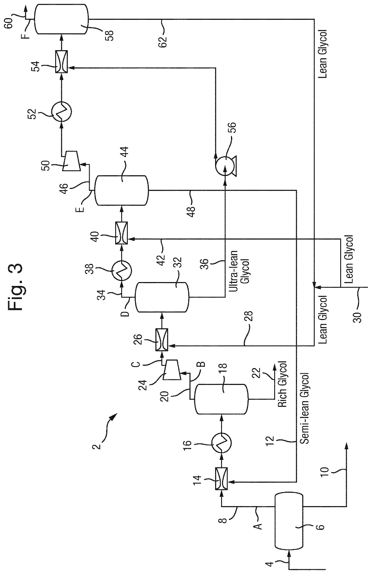
[0088]FIG. 3 schematically illustrates a subsea processing facility 2 for processing a multiphase hydrocarbon flow from a wellhead. The facility 2 is arranged to receive a multiphase hydrocarbon flow, separate the hydrocarbon flow into a gas phase and a liquid phase, and process at least the gas phase to a desired specification, for example a pipeline transportation specification. Various techniques for processing the liquid phase are known in the art and can be adopted as appropriate. Details of the liquid phase processing will not be described herein in detail.

[0089]In the following description, the terms “lean glycol”, “semi-lean glycol”, “ultra-lean glycol” and “rich glycol” are used. However, it should be understood that these terms are not intended to have specific meanings, but are used herein to give a general indication of the purity of the glycol at the various stages.

[0090]Within the art, the terms “lean glycol” and “rich glycol” are understood to refer, respectively, to ...


PUM

PropertyMeasurementUnit
temperatureaaaaaaaaaa
pressuresaaaaaaaaaa
temperatureaaaaaaaaaa

Abstract

A method of dehydrating a hydrocarbon gas stream including stripping water from a liquid desiccant stream using a water-undersaturated portion of the gas stream, drying the gas stream to extract the stripped water, and then further drying the partially-dried gas stream using the stripped desiccant to achieve a low water content level in the gas stream for pipeline transportation. In one embodiment, the liquid desiccant is supplied by a regeneration facility at a remote location and the liquid desiccant is returned to the regeneration facility for regeneration after drying the gas. In another embodiment, the regeneration of the desiccant is performed locally whereby the liquid desiccant is, after drying the gas, stripped again of water and reused locally.

Description

TECHNICAL FIELD[0001]The present invention relates to the dehydration of a hydrocarbon gas stream, in particular using a liquid desiccant such as a dry glycol.BACKGROUND OF THE INVENTION[0002]Production streams produced by remote or marginal offshore oil and gas fields, in addition to hydrocarbons, often contain liquid water and water in the gas phase. The produced hydrocarbon-containing fluid is warm when leaving the wellhead, generally in the range of 60-130° C. and, if the fluid is transported untreated over long distances and allowed to cool below the hydrate formation temperature, then hydrates will form. Hydrates are sometimes also referred to as clathrate hydrates, gas clathrates, gas hydrates, or clathrates.[0003]Hydrates are ice-like crystalline solids composed of water and gas. The hydrate formation temperature of a typically production stream is in the range of 20-30° C. for pressures of between 100-400 bar(a). Hydrate deposition on the inside wall of gas and oil pipeline...

Claims


Application Information

Patent Timeline
Patent Type & Authority Patents(United States)
IPC IPC(8): B01D53/00E21B43/36C10L3/10B01D53/14B01D53/26
CPCB01D53/1425B01D53/1493B01D53/263C10L3/106E21B43/36C10L2290/08C10L2290/545C10L2290/24C10L2290/06C10L2290/12B01D2252/2023C10L2290/58C10G70/048B01D2252/2021B01D2256/24B01D2257/80E21B43/34C10G70/04
Inventor JOHANNESSEN, EIVINDMARÅK, KNUT ARIDKOJEN, GRY PEDERSENFREDHEIM, ARNE OLAV
Owner DEN NORSKE STATS OLJESELSKAP AS
Why Eureka
Try Eureka