Aircraft fuel system

a fuel system and aircraft technology, applied in the direction of power plant fuel tanks, de-icing equipment, transportation and packaging, etc., can solve the problems of limited heat transfer rate, unsatisfactory heating, and clear safety issues, so as to reduce the ice formation in the fuel line, the effect of constant receiving power level and maximum system efficiency

Inactive Publication Date: 2014-11-04
AIRBUS OPERATIONS LTD
View PDF39 Cites 4 Cited by
  • Summary
  • Abstract
  • Description
  • Claims
  • Application Information

AI Technical Summary

Benefits of technology

[0008]A further aspect of the invention provides a method of suppressing ice formation in an aircraft fuel system, the fuel system including a fuel line carrying liquid fuel, and a microwave energy transmitter, the method comprising transmitting microwaves along the fuel line to energize water carried with the fuel in the fuel line.
[0010]The invention takes advantage of the large difference in dielectric constant between the water and the fuel in the fuel line. The dielectric heating effect on the fuel and on the water is proportional to their respective dielectric constants. Aviation fuel has a dielectric constant of around 2, whereas water has a dielectric constant of around 80. The microwaves therefore preferentially heat up the water to prevent it from freezing to ice when the bulk fuel temperature drops below the water freezing point (approx. 0 degrees Celsius). Ice has a dielectric constant of around 4, and so any ice which does form will also be preferentially heated by the microwaves to melt it. The overall heating effect on the fuel / water mixture in the fuel line is minimal (perhaps a few degrees Celsius) leading to a far more energy efficient anti-icing / de-icing system than the prior art heat exchangers.
[0012]The transmitter may be adapted to transmit at a wavelength tuned to the dimensions of the fuel line. In this way, the fuel line acts as a waveguide to maximise the efficiency of the system.
[0013]The fuel system may further comprise a microwave control system for controlling the output of the transmitter. The control system may include one or more microwave energy receivers. The or each receiver may have an antenna (preferably, a dipole antenna) disposed inside the fuel line. Preferably, two receivers are provided, one on either side of the transmitter. The transmitted energy will be partially absorbed by the water present in the fuel line. Energy that is not absorbed by the water, or elsewhere, will be present at the receiver(s). As the water content varies, the amount of energy absorbed by the water changes. Therefore, a signal from the receiver(s) may be used to measure and control the transmitted energy level, such that the transmitted energy is kept at an optimal level to suppress ice formation in the fuel line. In addition, the receivers prevent microwave leakage from the ends of the fuel line.
[0014]The control system may be adapted to maintain a substantially constant receive power level when the transmitter is operating. In this way, the heating effect remains constant. The amount of transmitted microwave energy is proportional to the amount of water in the fuel line such that the microwave energy per unit volume of water is constant. This ensures that the water is not heated up too rapidly by putting too much microwave energy per unit volume of water to cause high temperatures. When there is little or no water in the fuel line, the transmitted microwave energy would be very low so preventing energy wastage.

Problems solved by technology

The resulting ice particles may block fuel filters or otherwise interfere with the steady flow of fuel to the engines, thereby creating a clear safety issue.
The rate of heat transfer is limited and the heating is not uniform.

Method used


Image

  • Aircraft fuel system
  • Aircraft fuel system
  • Aircraft fuel system

Examples


Embodiment Construction

)

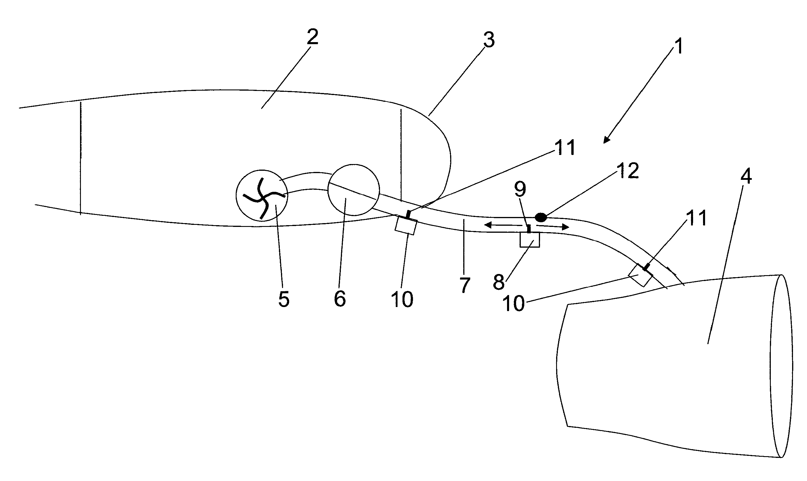
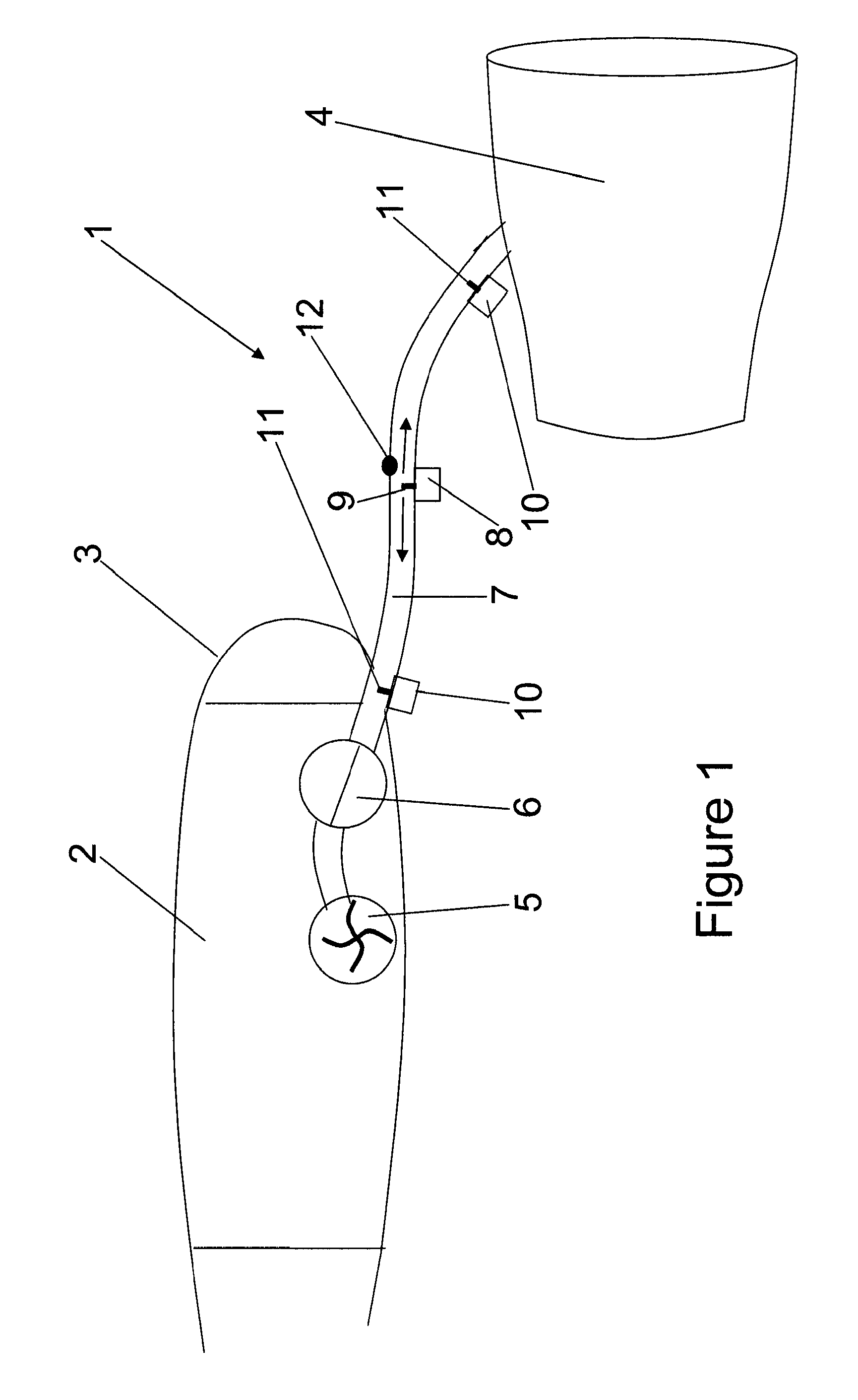
[0020]FIG. 1 shows an aircraft fuel system 1 for supplying liquid fuel from a fuel tank 2 in the aircraft wing 3 to a jet engine 4. The fuel system 1 includes a fuel pump 5 installed in the tank 2, a low pressure valve 6 (shown in its open position in FIG. 1) and a fuel line 7. The fuel line 7 supplies liquid fuel from the tank 2 to the engine 4. The engine 4 is mounted from the aircraft wing 3 by a pylon (not shown) of conventional type and the fuel line 7 passes through the pylon. The above described features of the fuel system 1 are entirely conventional.

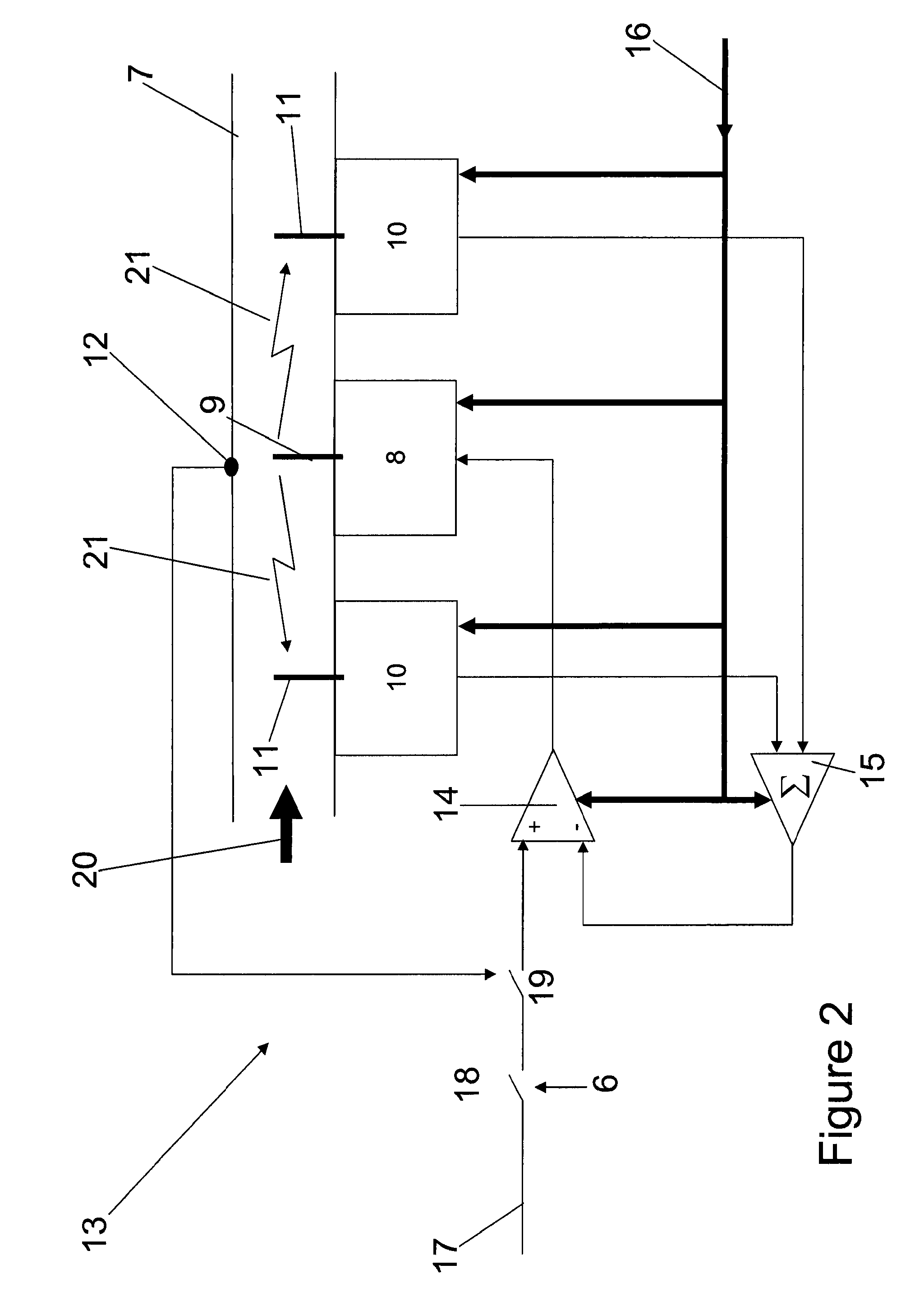
[0021]As can be seen from FIG. 1, the fuel system 1 further includes a microwave transmitter 8 having a dipole antenna 9 disposed within the fuel line 7. At each end of the fuel line 7 (between the valve 6 and the engine 4) is disposed a microwave receiver 10 having a dipole antenna 11 inside the fuel line 7. Mounted in the wall of the fuel line 7 is a temperature sensor 12. The transmitter 8, receivers 10 and sensor 12 are conn...


PUM


Abstract

An aircraft fuel system including a fuel line for carrying liquid fuel, and a microwave energy transmitter for energizing water carried in the fuel line. Also, a method of suppressing ice formation in an aircraft fuel system, the fuel system including a fuel line carrying liquid fuel, and a microwave energy transmitter, the method comprising transmitting microwaves along the fuel line to energize water carried with the fuel in the fuel line.

Description

RELATED APPLICATIONS[0001]The present application is based on, and claims priority from, British Application Number 091879.9, filed Oct. 13, 2009, the disclosure of which is hereby incorporated by reference herein in its entirety.FIELD OF THE INVENTION[0002]The present invention relates to a method of suppressing ice formation in an aircraft fuel system, and apparatus therefor.BACKGROUND OF THE INVENTION[0003]The presence of water in aircraft fuel has been a topic of concern for the aviation industry for many decades, since any contaminating water may freeze during long flights at high altitudes. The resulting ice particles may block fuel filters or otherwise interfere with the steady flow of fuel to the engines, thereby creating a clear safety issue.[0004]Fuel will absorb water and the quantity will depend on the ambient conditions such as temperature and humidity. The fuel will tend to precipitate any excess dissolved water when it is cooled to the temperatures prevailing at high ...

Claims


Application Information

Patent Timeline
Patent Type & Authority Patents(United States)
IPC IPC(8): B64D15/12B64D37/34B64D37/32
CPCB64D37/34B64D37/32
Inventor LAM, JOSEPH K-WTICHBORNE, FRANKLINMASTERS, SIMONPARMENTER, DAVID
Owner AIRBUS OPERATIONS LTD
Why Eureka
Try Eureka