Cam-lock actuating device for use in a locking coupling assembly that couples two tubular members

a technology of cam-locking and actuating device, which is applied in the direction of couplings, pipe joints, engine seals, etc., can solve the problems of pressurized fluid being ejected, pollution of the environment, and operator injuries, so as to facilitate the operation of two tubular members and quickly connect and disconnect them. , the effect of convenient operation

Active Publication Date: 2014-11-04
CHEN WATERSON
View PDF8 Cites 26 Cited by
  • Summary
  • Abstract
  • Description
  • Claims
  • Application Information

AI Technical Summary

Benefits of technology

[0006]An object of the present invention is to provide a cam-lock actuating device for use in a locking coupling assembly, which can be conveniently and safely operated to quickly connect and disconnect two tubular members.
[0007]According to this invention, the cam-lock actuating device includes an actuatable lever, an angularly positioning member, and leading and trailing releasably retaining members. The actuatable lever includes a head which is pivotally mounted on a lug unit of a female tubular coupler about a pivot axis, and which has a first forward surface region that extends angularly about the pivot axis, and an arm which is angularly displaceable among a fully locked position, where the arm is closer to a ledge of the female tubular coupler, an unlocked position, where the arm is remote from the ledge, and a partially locked position that is between the fully locked position and the unlocked position. The angularly positioning member is coupled to the head to be angularly displaceable therewith about the pivot axis, and has a second forward surface region extending angularly about the pivot axis. The leading and trailing releasably retaining members are respectively disposed to extend radially and independently from at least one of the first and second forward surface regions, and are configured such that, when the actuatable lever is displaced to the fully locked position, the leading releasably retaining member is brought into frictional engagement with a retained region of a male tubular coupler that is inserted into the female tubular coupler to thereby compress an elastomeric gasket into the compressed state, such that, when the actuatable lever is displaced to the partially locked position, the trailing releasably retaining member is brought into frictional engagement with the retained region so as to permit the elastomeric gasket to be held in a normal state, thereby relieving internal pressure in two tubular members, and such that, when the actuatable lever is displaced to the unlocked position, the trailing releasably retaining member is disengaged from the retained region to permit removal of the male tubular coupler from the female tubular coupler.

Problems solved by technology

However, since such locking coupling assembly is generally filled with a pressurized fluid in use, once the cam arms 10 are turned to the unlocking position by an operator, the male coupling tube 12 may burst from the internal pressure in the female coupling tube, which may cause injury to the operator.
Besides, the pressurized fluid may be ejected from the female coupling tube and pollute the environment.

Method used


Image

  • Cam-lock actuating device for use in a locking coupling assembly that couples two tubular members
  • Cam-lock actuating device for use in a locking coupling assembly that couples two tubular members
  • Cam-lock actuating device for use in a locking coupling assembly that couples two tubular members

Examples


first embodiment

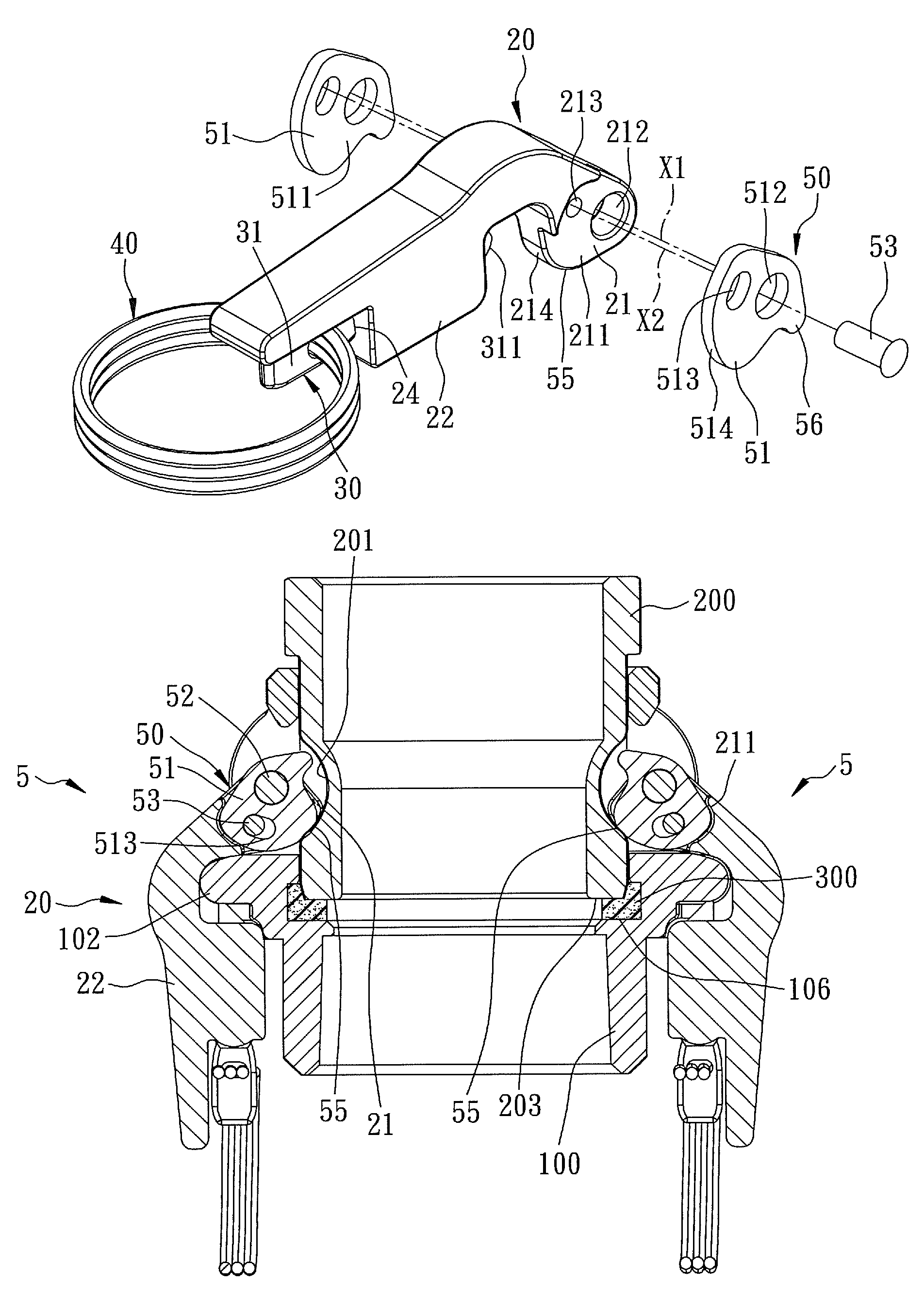
[0032]Referring to FIGS. 5 and 6, a cam-lock actuating device 5 according to the present invention is used in a locking coupling assembly to couple two tubular members (not shown). The locking coupling assembly includes a female tubular coupler 100 which has an inner peripheral seat 106, a male tubular coupler which has a tubular marginal portion 200 that is configured to be received in the female tubular coupler 100 and that has a retained region 201, such as an annular groove 201, and a surrounding abutment edge 203, an elastomeric gasket 300 which is disposed between the surrounding abutment edge 203 and the inner peripheral seat 106 to provide a fluid-tight seal when in a compressed state, two lug units 101 which are disposed on an outer tubular surface of the female tubular coupler 100, and two ledges 102 which are disposed adjacent to the lug units 101, respectively, and each of which has a cavity 103.

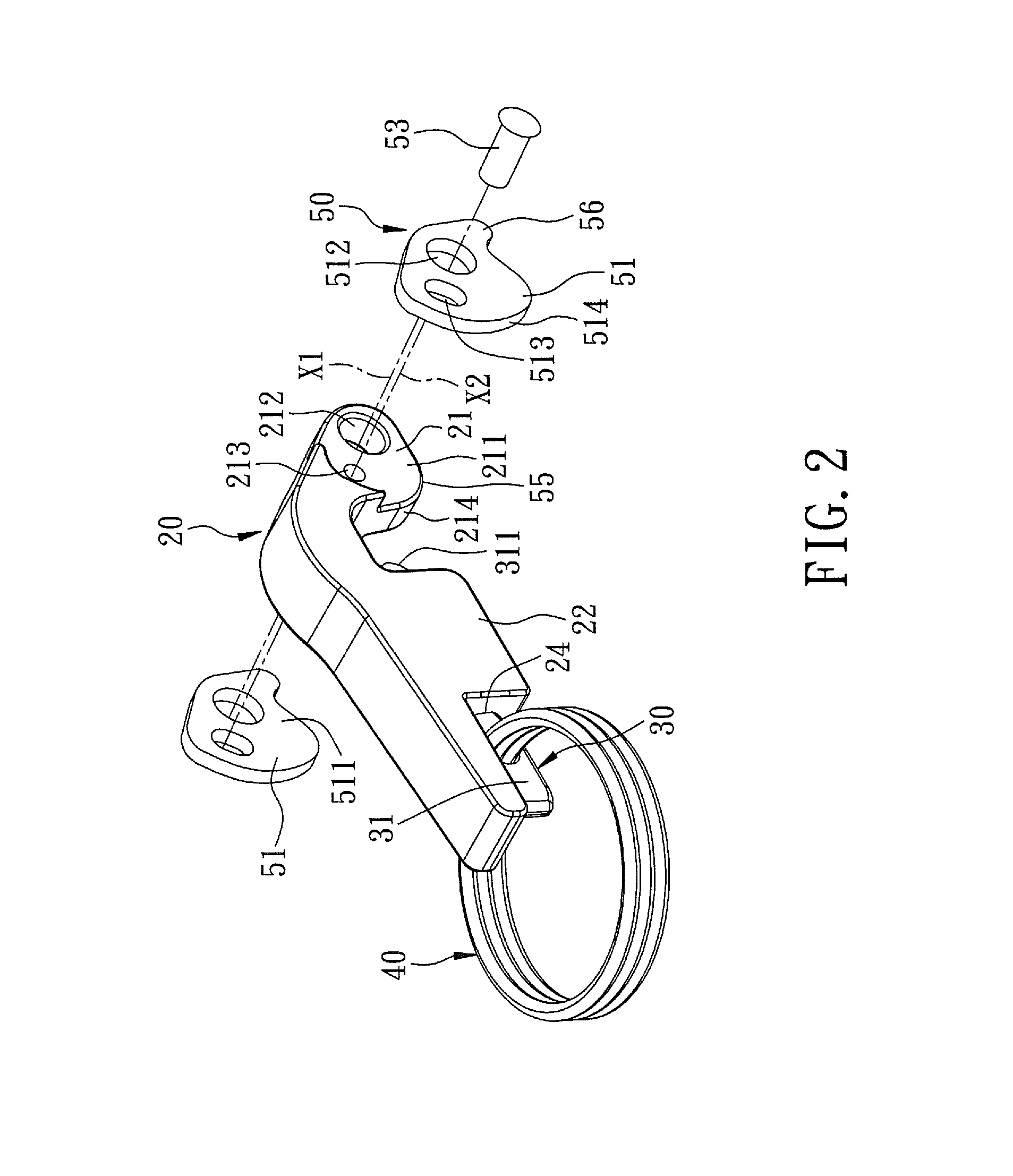
[0033]With reference to FIGS. 2 to 4, the cam-lock actuating device 5 of thi...

third embodiment

[0041]Alternatively, referring to FIG. 11, in the third embodiment, the position self-adjusting assembly includes an elongated slot 513 formed in the head 21, two journalled holes 515 respectively formed in the angularly positioning members 51 along the moving axis (X2), and a peg 53 extending through the elongated slot 513 to be journalled in the journalled holes 515.

fourth embodiment

[0042]Referring to FIG. 12, in the fourth embodiment, the position self-adjusting assembly includes two elongated slots 513 respectively formed in the angularly positioning members 51, and two pegs 53 integrally formed with the head 21 to be movably engaged in the elongated slots 513, respectively.


PUM


Abstract

A cam-lock actuating device for use in a locking coupling assembly that couples two tubular members, includes an actuatable lever having a head pivotally mounted on a female tubular coupler, an angularly positioning member coupled to be turned with the head, and leading and trailing releasably retaining members independently disposed on at least one of the head and the angularly positioning member such that, during turning of the actuatable lever to an unlocked position, the trailing releasably retaining member can be held in partially locking engagement with a male tubular coupler to prevent complete removal of the male tubular coupler from the female tubular coupler while permitting gradual relief of internal pressure.

Description

BACKGROUND OF THE INVENTION[0001]1. Field of the Invention[0002]This invention relates to a cam-locking coupling assembly that couples two tubular members, more particularly to a cam-lock actuating device for use in a locking coupling assembly which is operable to safely connect and disconnect two tubular members.[0003]2. Description of the Related Art[0004]Referring to FIG. 1, a conventional locking coupling assembly is shown to include a cylindrical body 1 connected to a female coupling tube (not shown), a male coupling tube 2 inserted into the cylindrical body 1 and fluid-tightly engaged therewith by means of a seal ring 3, and two cam arms 10 pivotably mounted on two lugs 101 of the cylindrical body 1 by pivot pins 112, respectively. Each of the cam arms 10 has a cam surface 111 extending into the cylindrical body 1 for engaging an annular grooved surface 201 of the male coupling tube 2 when the respective cam arm 10 is at a locking position. A spring-biased lock bolt 12 is mova...

Claims


Application Information

Patent Timeline
Patent Type & Authority Patents(United States)
IPC IPC(8): F16L37/18
CPCF16L37/18
Inventor CHEN, WATERSON
Owner CHEN WATERSON
Why Eureka
Try Eureka