
Focus scanning apparatus

a scanning apparatus and focus technology, applied in the field of three-dimensional (3d) scanning, can solve the problems of limited surface structure determination, large and expensive cmm, slow process, etc., and achieve the effect of fast scanning tim

Active Publication Date: 2014-11-04
3SHAPE AS
View PDF20 Cites 111 Cited by
  • Summary
  • Abstract
  • Description
  • Claims
  • Application Information

AI Technical Summary

Benefits of technology

The invention is a scanner that can be integrated into a small handheld device. The scanner is designed to identify and filter out blurry information while also scanning quickly.

Problems solved by technology

The advantages include great precision, but the process is slow and a CMM is large and expensive.
However, determination of the surface structure is limited to the parts of the surface that are illuminated by a spot.
However, the focal plane can only be adjusted by moving the specimen and the optical system relative to each other, i.e. closer to or further away from each other.
However, such a controlled spatial relation is not applicable to e.g. a hand held scanner.
These two images are used to extract the optical section, and the method is limited to acquisition of images from only two different illumination profiles.

Method used


Image

  • Focus scanning apparatus
  • Focus scanning apparatus
  • Focus scanning apparatus

Examples


Embodiment Construction

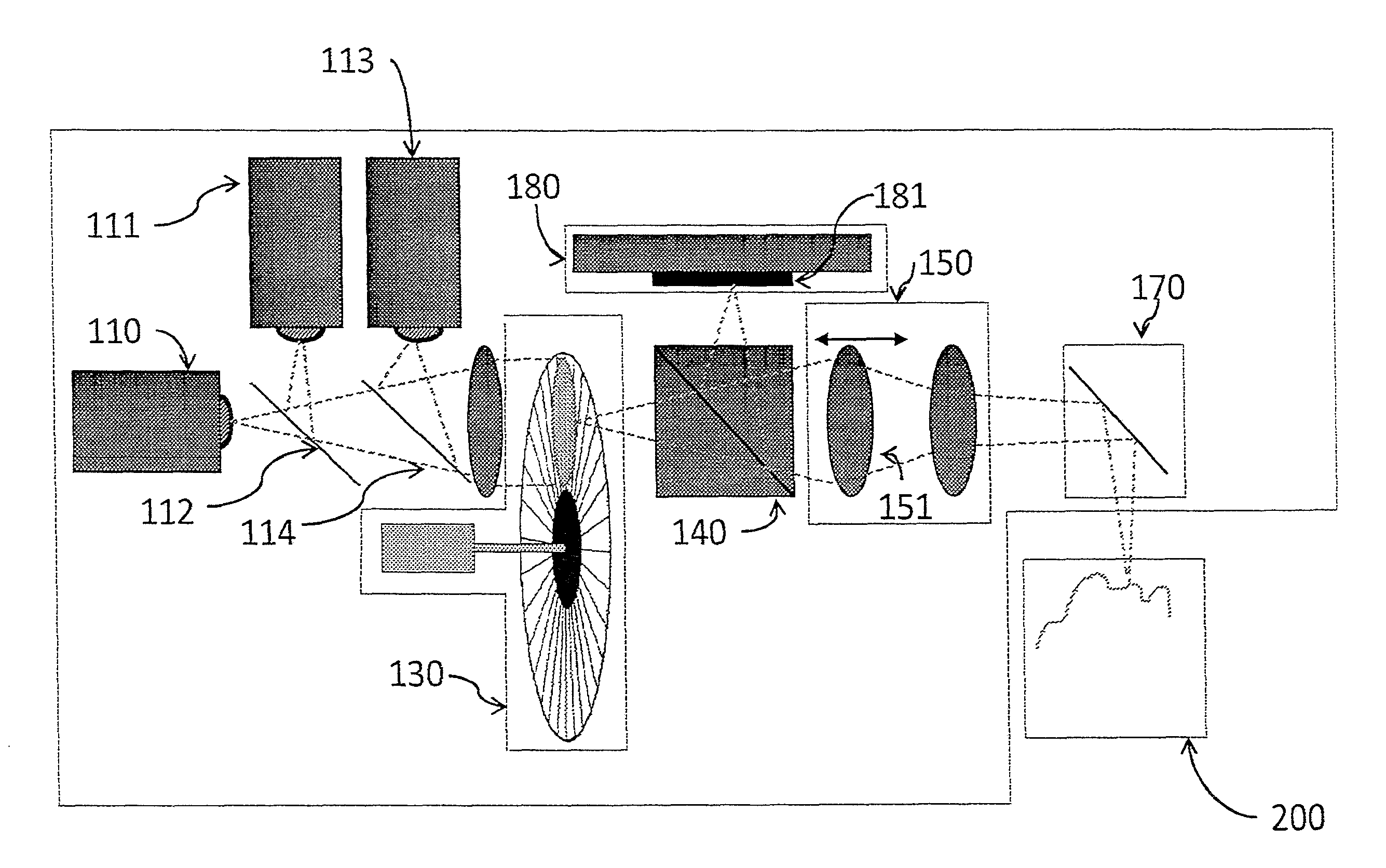
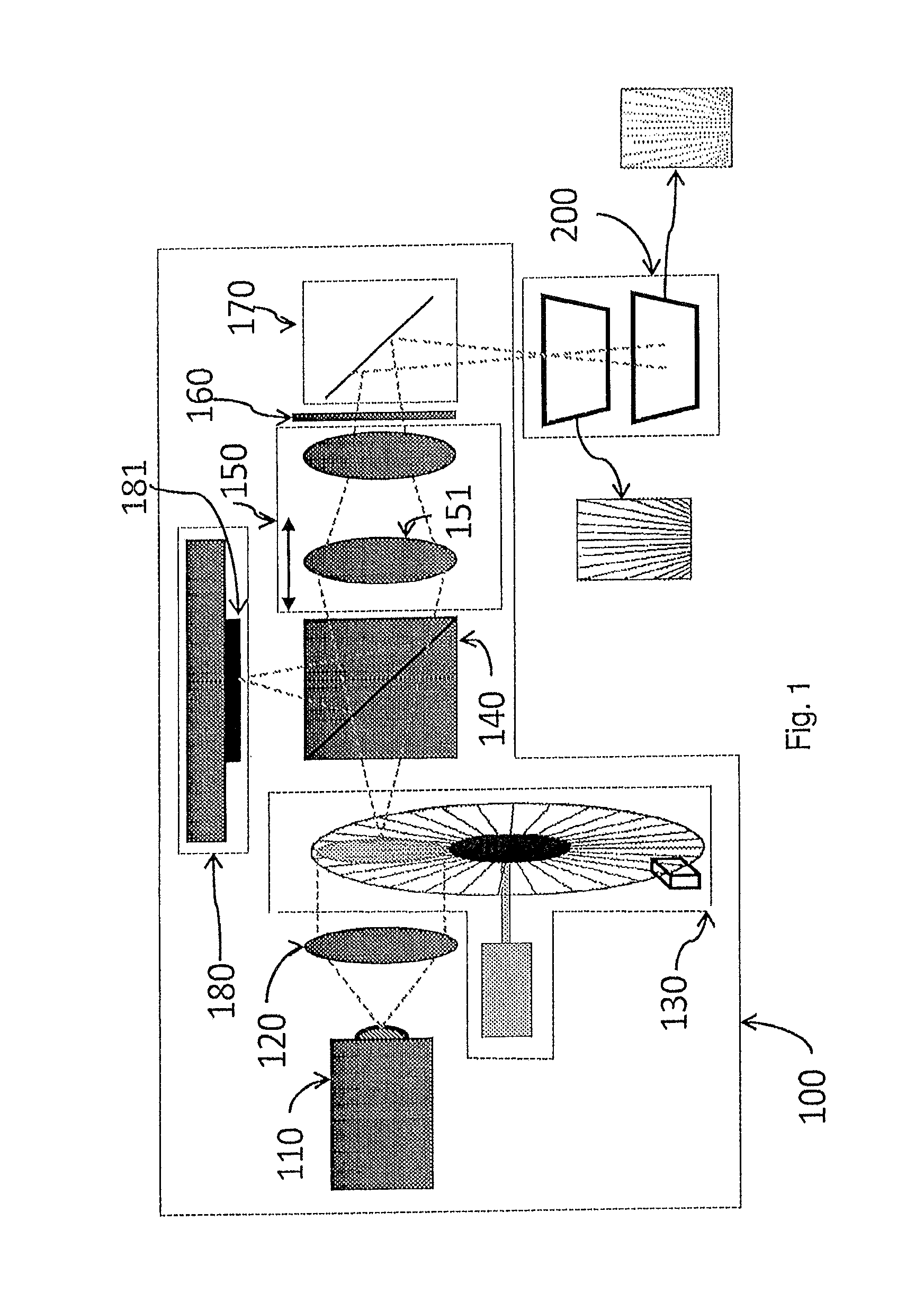
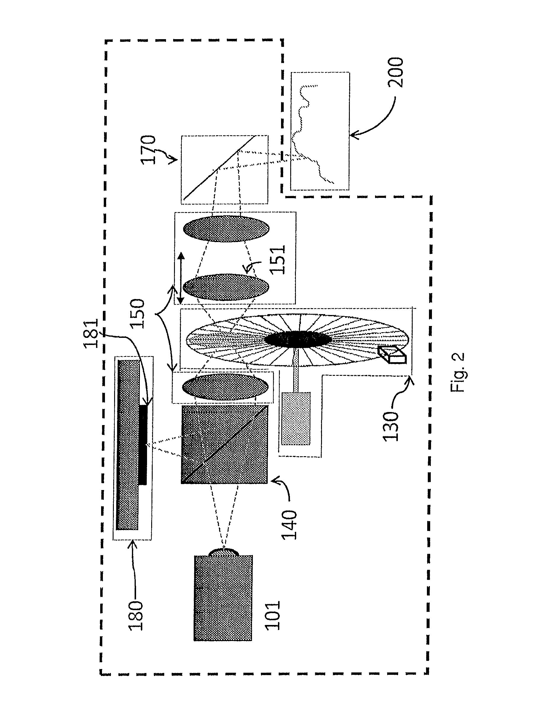
[0059]The scanner preferably comprises at least one beam splitter located in the optical path. For example, an image of the object may be formed in the camera by means of a beam splitter. Exemplary uses of beam splitters are illustrated in the figures.

[0060]In a preferred embodiment of the invention light is transmitted in an optical system comprising a lens system. This lens system may transmit the pattern towards the object and images light reflected from the object to the camera.

[0061]In a telecentric optical system, out-of-focus points have the same magnification as in-focus points. Telecentric projection can therefore significantly ease the data mapping of acquired 2D images to 3D images. Thus, in a preferred embodiment of the invention the optical system is substantially telecentric in the space of the probed object. The optical system may also be telecentric in the space of the pattern and camera.

Varying Focus

[0062]A pivotal point of the invention is the variation, i.e. scann...


PUM


Abstract

Disclosed is a handheld scanner for obtaining and / or measuring the 3D geometry of at least a part of the surface of an object using confocal pattern projection techniques. Specific embodiments are given for intraoral scanning and scanning of the interior part of a human ear.

Description

[0001]The present invention relates to an apparatus and a method for optical 3D scanning of surfaces. The principle of the apparatus and method according to the invention may be applied in various contexts. One specific embodiment of the invention is particularly suited for intraoral scanning, i.e. direct scanning of teeth and surrounding soft-tissue in the oral cavity. Other dental related embodiments of the invention are suited for scanning dental impressions, gypsum models, wax bites, dental prosthetics and abutments. Another embodiment of the invention is suited for scanning of the interior and exterior part of a human ear or ear channel impressions. The invention may find use within scanning of the 3D structure of skin in dermatological or cosmetic / cosmetological applications, scanning of jewelry or wax models of whole jewelry or part of jewelry, scanning of industrial parts and even time resolved 3D scanning, such as time resolved 3D scanning of moving industrial parts.BACKGRO...

Claims


Application Information

Patent Timeline
Patent Type & Authority Patents(United States)
IPC IPC(8): H04N13/02G01B11/25A61B5/00A61B5/107
CPCA61B5/0068G01B2210/58G01B11/2513A61B5/4547G01B11/2518A61B5/1077H04N13/0296H04N13/296A61B5/1075A61B5/1076
Inventor FISKER, RUNEOJELUND, HENRIKKJ.AE BUTTED.R, RASMUSVAN DER POEL, MIKEQAZI, ARISH A.HOLLENBECK, KARL-JOSEF
Owner 3SHAPE AS
Learn More