Optical attachment for reducing the focal length of an objective lens

a technology of optical attachment and objective lens, which is applied in the field of optical attachment for reducing the focal length of an objective lens, can solve the problems of reducing the “speed” of the objective plus teleconverter system, reducing the optical performance of the system, and magnifying aberration, so as to reduce the focal length and focal ratio, reduce the size of the format, and reduce the effect of the working distan

Inactive Publication Date: 2014-11-04
CALDWELL PHOTOGRAPHIC
View PDF6 Cites 24 Cited by
  • Summary
  • Abstract
  • Description
  • Claims
  • Application Information

AI Technical Summary

Problems solved by technology

Unfortunately, teleconverters have several undesirable side effects, including: 1) they increase the focal ratio of the objective lens, thus reducing the “speed” of the objective plus teleconverter system; and 2) they magnify the aberrations of the objective lens, thus reducing the optical performance of the system.
Despite these potential advantages, rear attachments for reducing the focal length of photographic objectives are notably uncommon due to a number of design and implementation challenges.
Chief among these challenges is the fact that rear focal reducers of fairly simple construction tend to reduce the working distance of the system to a remarkable degree, thus making them unsuitable for use with single lens reflex cameras.
An elaborate reverse-telephoto construction for eliminating this defect is disclosed in U.S. Pat. No. 5,499,069, but this solution is very complex and is not suitable for large apertures (e.g., small aperture ratios).
Another problem with rear focal reducers is that they inherently suffer from large undercorrected field curvature.
The focal reducers disclosed in U.S. Pat. No. 4,264,151 also suffer from a very large amount of barrel distortion.
However, none of the adapters developed to-date reduce the focal length of the attached 35 mm SLR lens.

Method used


Image

  • Optical attachment for reducing the focal length of an objective lens
  • Optical attachment for reducing the focal length of an objective lens
  • Optical attachment for reducing the focal length of an objective lens

Examples


example 1

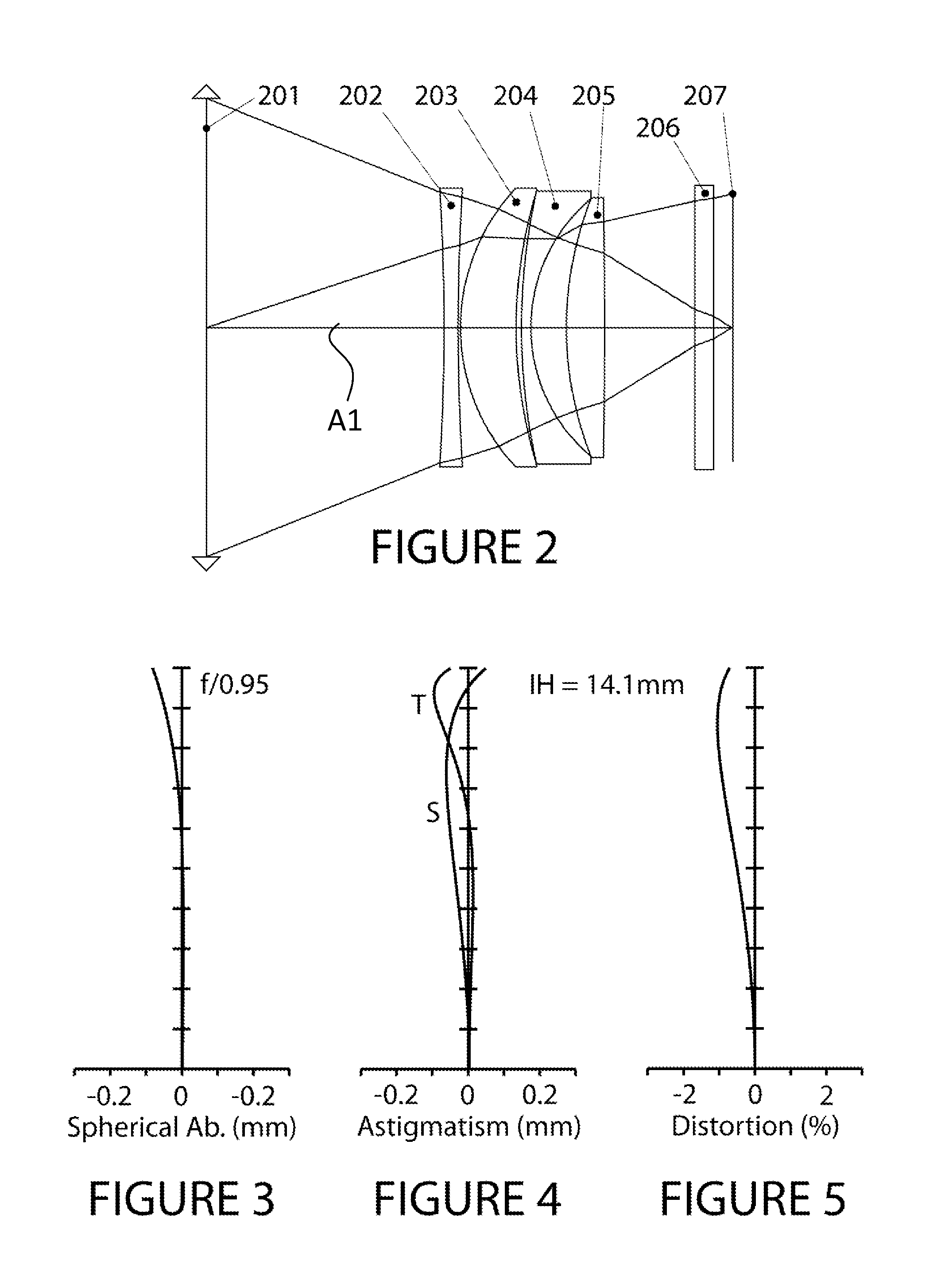
[0068]FIG. 2 is a layout of Example 1 of the present disclosure, which is a focal reducing attachment having a focal length of 83.1 mm and a magnification of 0.71×. In order to evaluate optical performance, a paraxial lens 201 having a focal length of 60 mm is placed 25 mm toward the object side of the optical attachment. Although the aperture stop for the attachment is coincident with the paraxial lens for the purpose of aberration evaluation, it may be moved axially over a wide range of values so that it will correspond with the exit pupil location of an attached objective lens. In practice, the attached objective lens will normally determine the actual location of the aperture stop and system exit pupil since it will generally have an iris mechanism. Example 1 is designed to be compatible with a wide range of objective lens exit pupil distances.

[0069]The focal reducing attachment itself comprises four optical elements in order from the object side to the image side: 1) a weak neg...

example 2

[0075]FIG. 6 is a layout of Example 2 of the present disclosure, which is a focal reducing attachment having a focal length of 102.6 mm and a magnification of 0.71×. In order to evaluate optical performance, a paraxial lens 601 having a focal length of 60 mm is placed 24 mm toward the object side of the optical attachment. As with Example 1, the aperture stop for the attachment is coincident with the paraxial lens for the purpose of aberration evaluation, but it may be moved axially over a wide range of values so that it will correspond with the exit pupil location of an attached objective lens. In practice, the attached objective lens will normally determine the actual location of the aperture stop and system exit pupil since it will generally have an iris mechanism. Example 2 is designed to be compatible with a wide range of objective lens exit pupil distances.

[0076]The focal reducing attachment itself comprises four optical elements in order from the object side to the image side...

example 3

[0082]FIG. 10 is a layout of Example 3 of the present disclosure, which is a focal reducing attachment having a focal length of 84.6 mm and a magnification of 0.71×. In order to evaluate optical performance, a paraxial lens 1001 having a focal length of 60 mm is placed 25 mm toward the object side of the optical attachment. Although the aperture stop for the attachment is coincident with the paraxial lens for the purpose of aberration evaluation, it may be moved axially over a wide range of values so that it will correspond with the exit pupil location of an attached objective lens. In practice, the attached objective lens will normally determine the actual location of the aperture stop and system exit pupil since it will generally have an iris mechanism. Example 3 is designed to be compatible with a wide range of objective lens exit pupil distances.

[0083]The focal reducing attachment itself comprises four optical elements in order from the object side to the image side: 1) a weak n...


PUM


Abstract

An optical attachment configured to be operably attached to the image side of an objective lens to reduce the focal length and focal ratio of the objective lens. The focal-reducing attachment includes four lens elements and has a magnification of between 0.5 and 1. The focal-reducing lens can work with objective lenses having relatively large working distances for a large format size as well as with cameras having a smaller format size and relatively small permissible working distance.

Description

CLAIM OF PRIORITY[0001]This application claims the benefit of priority under 35 U.S.C. §119(e) of U.S. Provisional Application Ser. No. 61 / 573,847, filed on Sep. 13, 2011, which application is incorporated by reference herein.FIELD[0002]The present disclosure is directed to an optical attachment placed on the image side of an objective lens in order to reduce the focal length and focal ratio of that objective lens. The present invention is particularly suitable for adapting objective lenses designed with a relatively large working distance for a large format size to cameras having a smaller format size and relatively small permissible working distance.BACKGROUND ART[0003]Lenses designed for 35 mm single lens reflex cameras (“SLR lenses”) are well known in the art, and millions of such lenses have been manufactured since the late 1950's. An important feature of these lenses is that they must have a working distance that is sufficiently large to allow a reflex mirror to swing into the...

Claims


Application Information

Patent Timeline
Patent Type & Authority Patents(United States)
IPC IPC(8): G02B15/177G02B13/18G03B17/00G02B9/34
CPCG02B13/18G02B15/177G02B9/34
Inventor CALDWELL, J. BRIANBITTNER, WILFRIED
Owner CALDWELL PHOTOGRAPHIC
Why Eureka
Try Eureka