
Storage system

a storage system and automatic tiering technology, applied in the direction of memory adressing/allocation/relocation, input/output to record carriers, instruments, etc., can solve the problems of losing the long-cycle stable tier 1 hit rate, relocating a large quantity of pages whose load decreases, and not being able to follow up on sudden and short-cycle load shorter than the above cycle, etc., to achieve the effect of improving the data hit ra

Active Publication Date: 2014-11-04
HITACHI LTD
View PDF12 Cites 8 Cited by
  • Summary
  • Abstract
  • Description
  • Claims
  • Application Information

AI Technical Summary

Benefits of technology

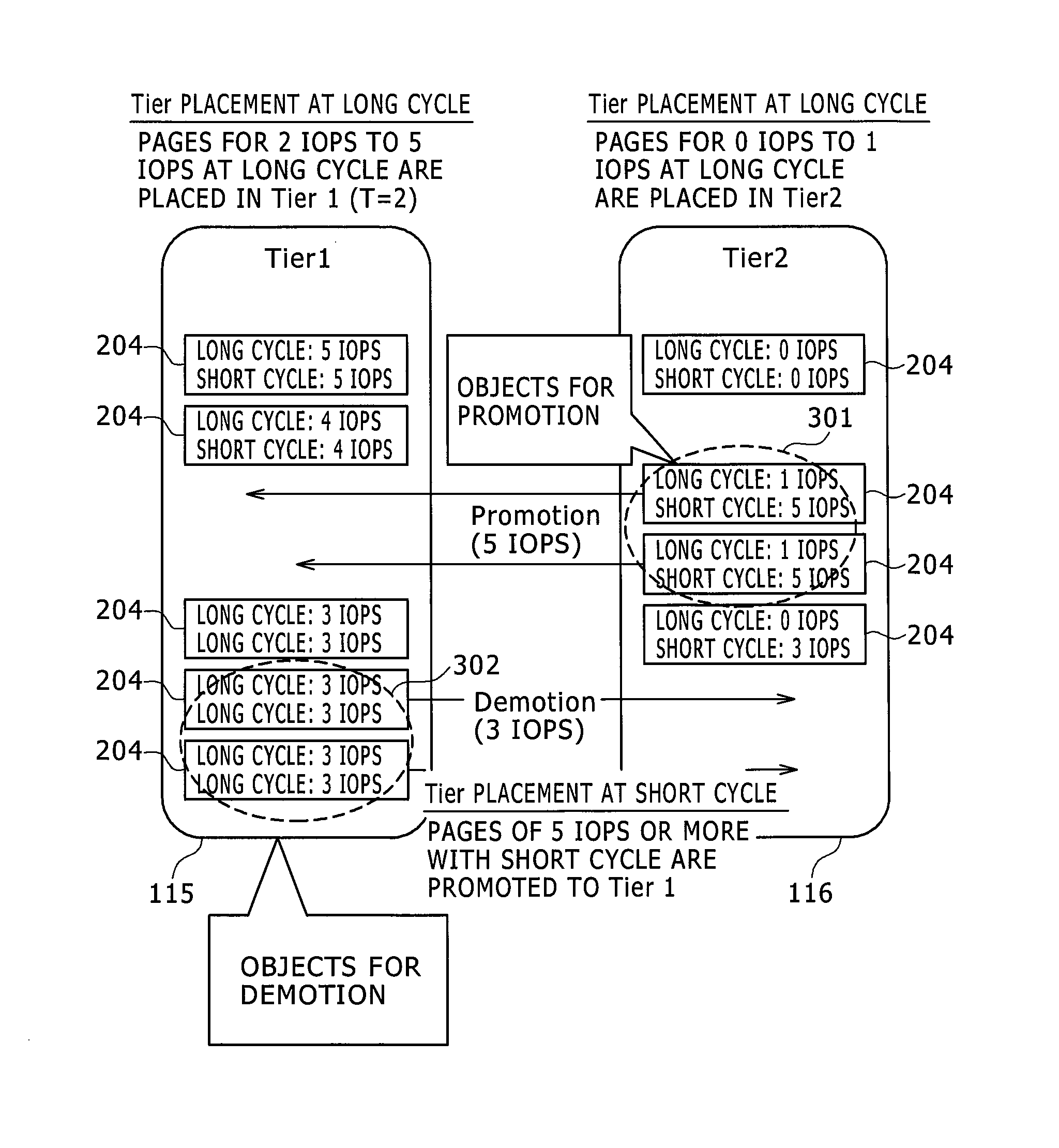
The invention allows for organizing data on different levels while considering sudden changes in demand. It also helps improve the chance of hitting data in high levels.

Problems solved by technology

However, the technology disclosed in US Patent Application Publication No. 2012 / 0246386A1 has the problem that due to the sampling of the monitor at each specified cycle and the relocating, following up on a sudden and short-cycle load shorter than the above cycle was impossible.
Moreover, attempting to simply set a short cycle on an order between several seconds and several minutes, results in relocating a large quantity of pages whose load diminishes in a short period, losing the long-cycle stable Tier 1 hit rate.
Other issues are an increasingly large processing load on the controller that counts each monitor cycle, and the effect of a large load (drop in performance and drop in SSD endurance) on the cache and drive due to an increase in the page migration volume.

Method used


Image

  • Storage system
  • Storage system
  • Storage system

Examples


first embodiment

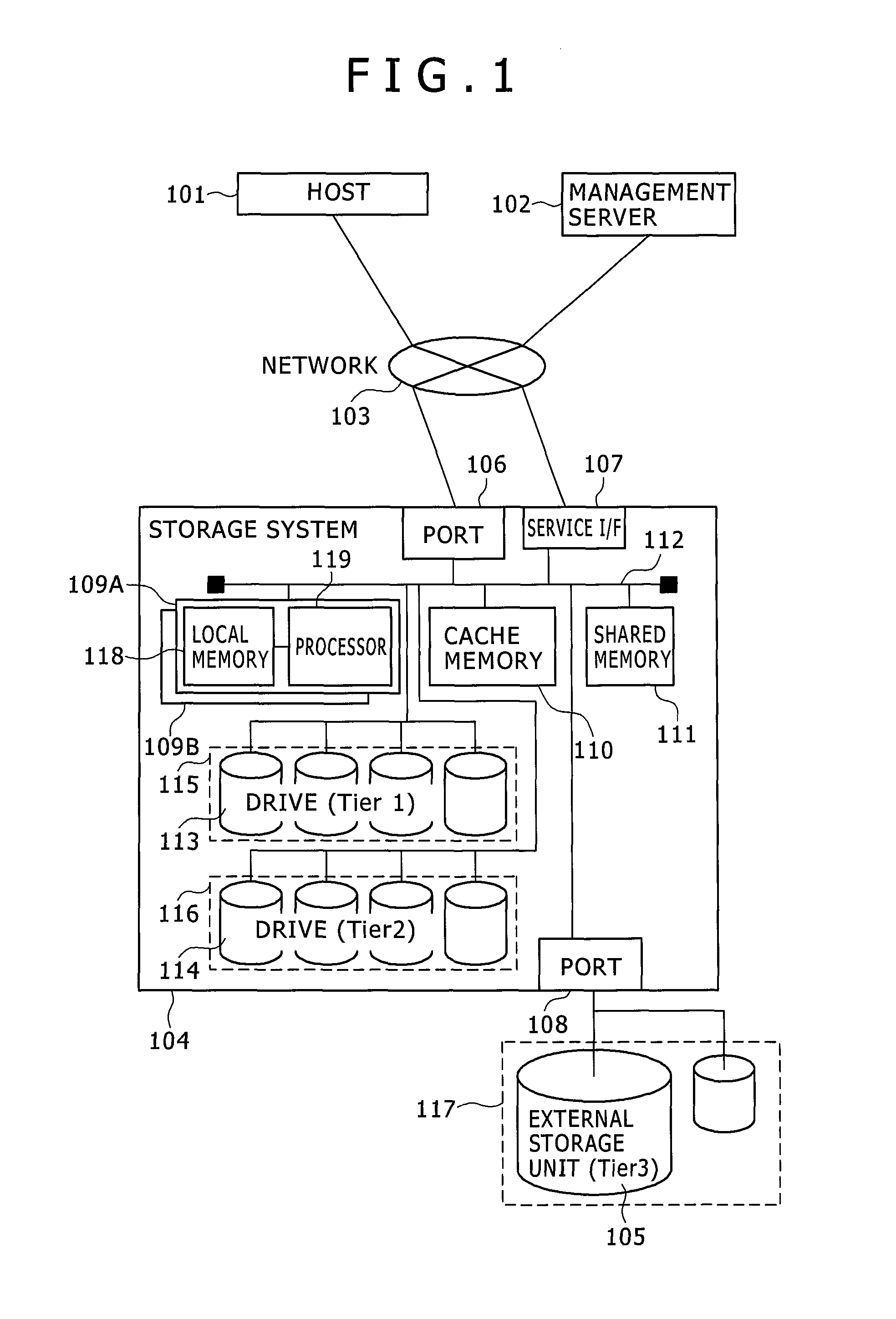
[0038]FIG. 1 is a block diagram showing a typical structure of the computer system of the present invention. A host 101 is for example configured from an ordinary server, and is coupled to the port 106 of the storage system 104 by way of a network 103. The host 101 issues the data read and write commands on the storage system 104, and the storage system 104 performs reading or writing of the data according to that command. The network 103 is configured for example by SAN (Storage Area Network) or Ethernet (registered trademark), etc. A management server 102 is coupled by way of the network 103 to the service I / F port 107 or port 108 of the storage system 104. The storage administrator utilizes the management server 102 to send commands for each type of setting and control required for operating the storage system to the storage system 104. If coupled to an external storage unit 105, the external storage unit 105 is coupled to the port 108 of the storage system 104. The external stor...

fourth embodiment

[0090]First of all, the monitor count-up processing starts when this (monitor rewriting & tier decision processing) starts up (S1701). More specifically, for entries in the page monitor tables corresponding to the relevant page, the long-cycle IO counter 902 counts up in the sampling phase of the current cycle, and the temporary counter 903 counts up. During the first IO, the current time is stored at the prior temporary counter expiry time. After the monitor count-up, when the temporary counter 903 reaches N, the short-cycle IOPS is calculated from (current time−prior temporary counter expiry time)÷N. The processing afterwards proceeds to the tier decision processing (S1703). If the temporary counter does not reach N or more, then the processing ends. In the method for calculating this short-cycle IOPS, the short cycle relative to a specific cycle will disappear if (current time−prior temporary counter expiry time) exceeds the specified cycle. Therefore, the measurement may be stop...

second embodiment

[0100]One example of the tier decision method is disclosed as the

[0101]FIG. 19 is a flowchart for expressing the operation in the tier decision processing of the present embodiment executed in S1703 in FIG. 17.

[0102]First of all, when this processing starts up, the (A) demotion judgment is executed (S1901). This decision processing decides whether or not to execute demotion processing on the relevant page as the demotion target. The details are described while referring to FIG. 20. If the result of the decision processing is that demotion is required (Y in S1902) then the page movement request is returned (S1905) and the processing ends. If the decision results are that demotion is not needed in S1902) then a (B) promotion decision is implemented (S1903). The decision processing decides whether or not the relevant page is a promotion target. The details are described while referring to FIG. 21. When the result is that promotion is required (Y in S1904), the page movement request is ...


PUM


Abstract

A storage system monitors the first access frequency of occurrence which is the access frequency of occurrence from a host device during a first period, and the second access frequency of occurrence which is the access frequency of occurrence from a host device during a second period shorter than the first period. Along with performing data relocation among the tiers (levels) in the first period cycle based on the first access frequency of occurrence, the storage system performs a decision whether or not to perform a second relocation based on the first access frequency of occurrence and the second access frequency of occurrence, synchronously with access from a host device. Here the threshold value utilized in a decision on whether or not to perform the first relocation is different from the threshold value utilized in a decision on whether or not to perform the second relocation.

Description

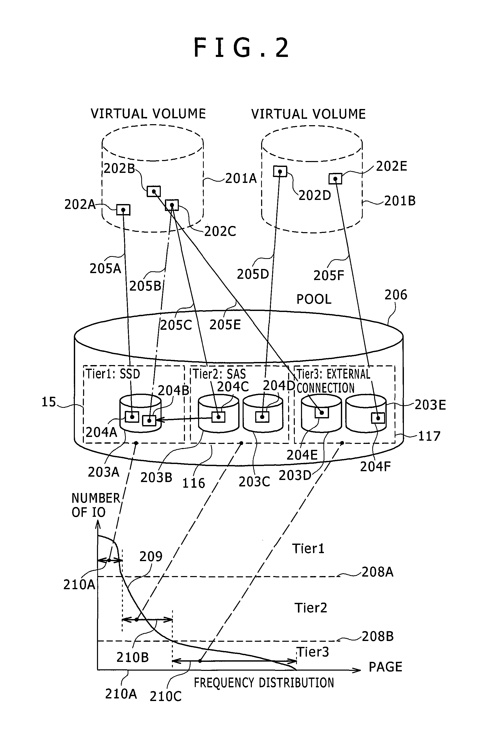
BACKGROUND[0001]The present invention relates to an automated tiering control for a storage system and containing a plurality of levels.[0002]Larger data volumes and diversified types of data as well as a wide variety of storage media within storage devices due to the spread of high-speed SSD (Solid State Drives) that are faster than HDD (hard disk drive) has made the placing of data into the appropriate storage media tier (or level) a difficult task. One technique for resolving this issue is an automated storage tiering function for storage devices to automatically store the data in the appropriate storage media according to the access frequency of occurrence of the data.[0003]An automated tiering control function generally migrates the page to an upper tier (or level) (called promotion) when there is a large IO (input / output) frequency of occurrence on a page, and migrates the page to a lower tier (or level) (called demotion) when there is a small IO frequency of occurrence within...

Claims


Application Information

Patent Timeline
Patent Type & Authority Patents(United States)
IPC IPC(8): G06F12/00G06F3/06G06F12/02G06F13/00G06F13/28G06F12/1009
CPCG06F3/061G06F3/0685G06F3/0649G06F12/0246G06F12/1009G06F3/0604G06F3/0647G06F3/0662G06F3/0683G06F2003/0697G06F2212/7201G06F3/06G06F3/0679G06F3/0665G06F3/0653G06F3/0613
Inventor AKUTSU, HIROAKIYAMAMOTO, AKIRAHOMMA, SHIGEOYAMAMOTO, MASANOBUOHIRA, YOSHINORI
Owner HITACHI LTD
Learn More