Tension tool

a technology of a tool and a tool body, which is applied in the direction of wire tools, manufacturing tools, rod connections, etc., can solve the problems of difficult disposing of coupling tools, difficult hooking, and increasing the number of components of the turnbuckle, so as to facilitate the operation of fastening and shorten the length of the fastening using the tool. , the effect of easy sliding

Inactive Publication Date: 2014-11-11
TERANISHI RYOUHEI
View PDF14 Cites 15 Cited by
  • Summary
  • Abstract
  • Description
  • Claims
  • Application Information

AI Technical Summary

Benefits of technology

[0029]According to the first invention of the present invention, the nut fastened from the end portion of the shaft body is apart from the virtual line connecting the first receiving portion with the second receiving portion and can be fastened in the easy-to-work state where the nut is apart from the object to move closer, and the fastening operation can be facilitated even if a tool, e.g., a ratchet wrench or an electric torque wrench is used. When the gap between the shaft body and the cylindrical body has a small width, the cylindrical body is not caught by the shaft body, and the cylindrical body can be easily slid along the shaft body. Further, when the gap between the shaft body and the cylindrical body is a width that enables inclining the shaft body in the cylindrical body, the position of the cylindrical body can be temporarily held, the nut attached to the shaft body can be rotated with fingertips of an operator and fastened until it comes into contact with the end portion of the cylindrical body, the operation performed with use of the ratchet wrench or the electric torque wrench alone is the final fastening operation, the length for fastening using the tool can be shortened, and the nut fastening operation can become more easy and efficient as advantageous effects. The operation of performing rotation with fingertips may be omitted as a matter of course. In this case, the operation of fastening the nut with use of the electric torque wrench can be smoothly carried out.
[0030]According to the second invention of the present invention, the inner surface corner portion of the cylindrical body can be hooked on the screw thread of the shaft body, the position of the cylindrical body can be temporarily held, the length for fastening using the tool can be shortened, and the operation of fastening the nut can be more facilitated.
[0031]According to the third invention of the present invention, even if the inclination of the shaft body is small in the cylindrical body, when the second locking portion is slid toward the first locking portion side with the linear material being caught on the first locking portion and the second locking portion, the engagement portion formed on the inner side of the cylindrical body is caught on the screw thread of the shaft body, and the shaft body is temporarily locked and held. Moreover, the cylindrical body is slid until slack is eliminated without operating the nut with use of a the tool, the nut is rotated and preliminarily fastened by fingertips, then the nut can be fastened by using the tool only on the final fastening stage, and hence the fastening operation can become efficient. The operation of performing rotation with fingertips may be omitted as a matter of course. Even in this case, the operation of fastening the nut by the electric torque wrench can be smoothly carried out.
[0032]According to the fourth invention of the present invention, the shaft body is solely held or the shaft body is held together with the cylindrical body to determine a direction of the distal end of the hook portion, and the distal end of the hook portion can be easily inserted and hooked in the link of the chain or the ring of the wire member having the ring formed at the end portion thereof.
[0033]According to the fifth invention of the present invention, at the time of inserting the hook portion as the first locking portion into the ring, the shaft body of the tension tool does not interfere with the linear material, and the first locking portion of the tension tool can be easily hooked on a halfway position of the linear material stretched with less slack.
[0034]According to the sixth invention of the present invention, at the time of sliding the cylindrical body toward the first locking portion side, the end portion of the cylindrical body on the first locking portion side is not hooked on the screw thread of the shaft body, and the cylindrical body can be easily slid.

Problems solved by technology

According to this technology, the length between the coupling tools at both the ends of the turnbuckle can be easily adjusted, whereas there is a problem that the number of components constituting the turnbuckle increases.
However, in case of a chain stretched with less slack, at the time of engaging the hook on the bolt head side with the upper link, the hook on the bolt distal end side that is in the freely fitted state interferes with the other link and rotates, and hence the hook is hard to be hooked.
Moreover, after the hook on the bolt head side is hooked, the hook on the bolt distal end side must be held with one hand, a position of the link of the chain placed on the bolt distal end side must be adjusted with the other hand while sliding the bolt shaft along the cylindrical body on the bolt head side, the hook on the bolt end side must be fitted to the link while paying attention to prevent the hook on the bolt head side which has been hooked before the counterpart from coming off the link, and hence there is a problem that disposing the coupling tool is difficult.

Method used


Image

  • Tension tool
  • Tension tool
  • Tension tool

Examples


embodiment 1

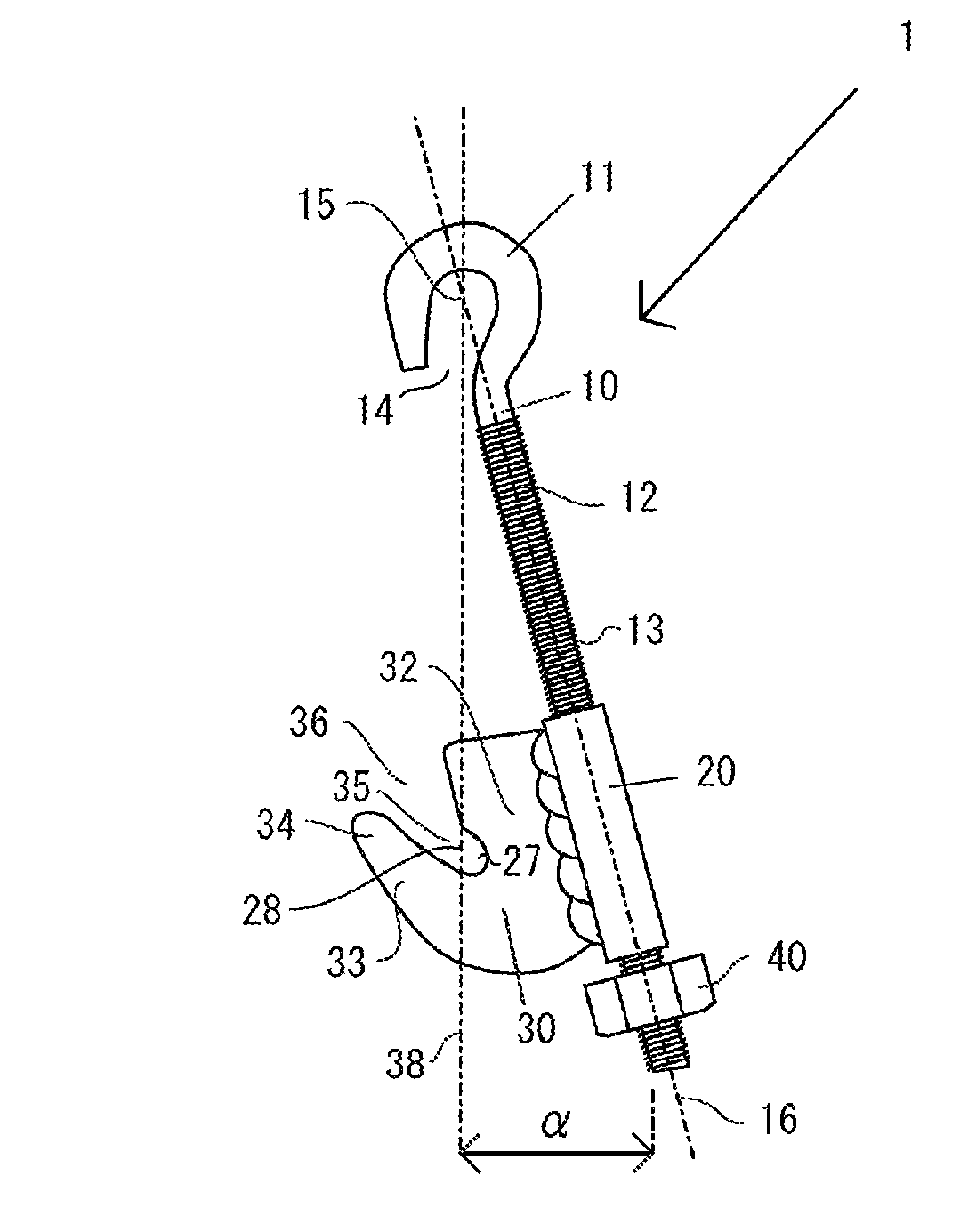
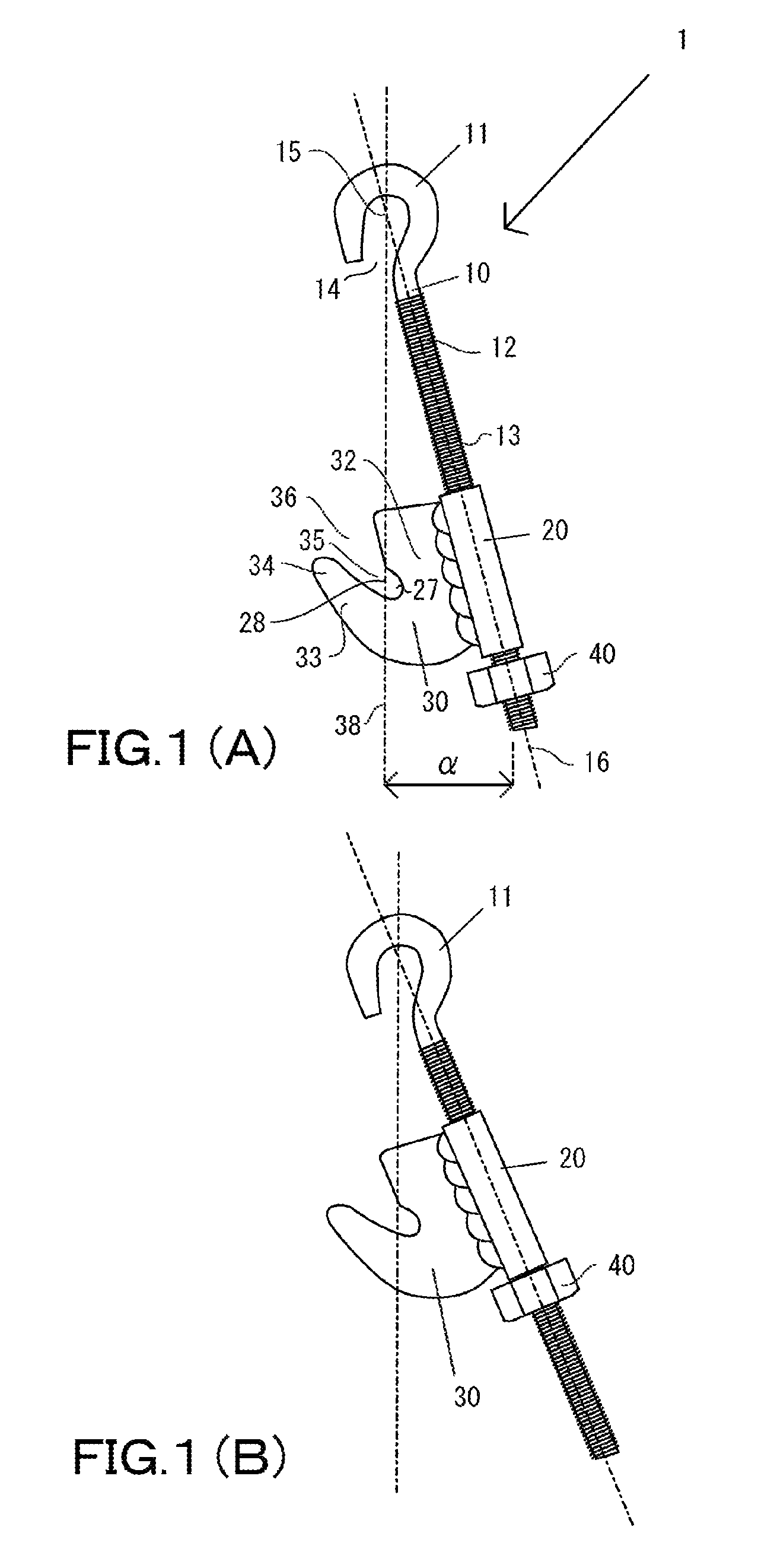
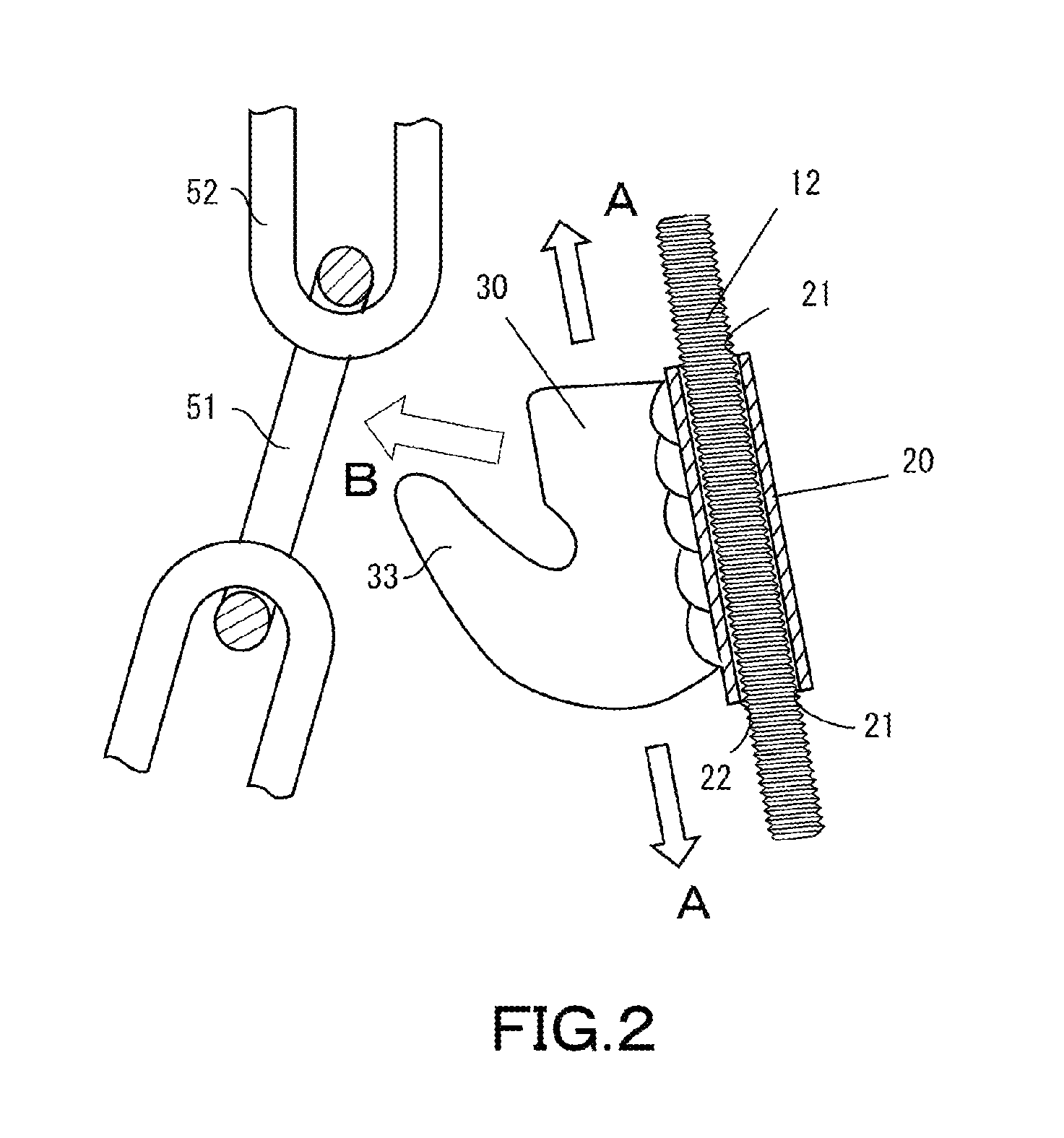
[0045]In Embodiment 1, an embodiment of a tension tool that binds a position of a concrete form will now be described with reference to FIG. 1 to FIG. 5. FIG. 1 is a side elevation of a tension tool, FIG. 2 is a cross-sectional view of a primary part when a gap between a shaft body and a cylindrical body is small, FIG. 3 is an explanatory view of an outline of attachment in a state that the tension tool is attached to a lateral side of the concrete form, FIG. 4 is an explanatory view of an attachment process of the tension tool when a gap between a shaft body and a cylindrical body is large, and FIG. 5 is an explanatory view of final fastening of the tension tool.

[0046]A configuration of a tension tool 1 will now be described with reference to FIG. 1. FIG. 1(A) shows a state before tension, and FIG. 1(B) shows a state after tension. The tension tool 1 is formed of a shaft body 10, a cylindrical body 20 having a locking piece 30 as a second locking portion secured on a lateral side t...

embodiment 2

[0059]In Embodiment 2, a description will now be given as to a tension tool 2 in which a distal end of a hook portion 11 is bent toward the lateral side from a position near a top portion of a bent portion with respect to a plane along which the hook is bent and extended from a proximal end portion of the hook portion with reference to FIG. 6. FIG. 6(A) is a front view of the tension tool 2, and FIG. 6(B) is a side elevation of the tension tool 2. In this embodiment, a distal end portion 111 of the hook portion 11 formed at the distal end of the shaft portion is bent toward the lateral side with respect to a plane 113 along which the hook portion 11 is bent and extended from a proximal end portion 112 (see FIG. 6(B)). Like reference numerals denote portions having the same configuration as those in Embodiment 1, and a description thereof will be omitted.

[0060]When a chain has less slack and a stretching direction of the chain is parallel to a direction of a shaft portion of the tens...

embodiment 3

[0062]In Embodiment 3, a description will be given as to an embodiment where an engagement portion is formed on an end portion of a second locking portion side inner surface of a cylindrical body on a nut side with reference to FIG. 7. FIG. 7 is an explanatory view of a tension tool 3 having an engagement portion 23 formed in a cylindrical body. FIG. 7(A) is a partial cross-sectional view showing a tension tool before attachment, FIG. 7(B) is an enlarged perspective view of a primary part showing a lower portion of a cylindrical portion from a lower side in perspective, and FIG. 7(C) is a partial cross-sectional view showing a state that the cylindrical body is temporarily locked to a screw portion of a shaft body.

[0063]In the tension tool 3, a lower open end portion of a cylindrical body 20 on a claw portion side is pressed inward, and a convex portion is formed on the inner side of the cylindrical body, thereby forming an engagement portion 23 (see FIG. 7(B)). Furthermore, the ins...


PUM

PropertyMeasurementUnit
tensionaaaaaaaaaa
widthaaaaaaaaaa
pressureaaaaaaaaaa

Abstract

A tension tool includes: a shaft body that has a first locking portion formed at one end portion thereof and a screw portion formed from the other end portion thereof to a screw portion; a cylindrical body that holds the shaft body to interpose a gap therebetween and has a second locking portion attached to a lateral side thereof; and a nut that is disposed to the screw portion in contact with the other end portion side of the cylindrical body and adjusts a separation length between the first locking portion and the second locking portion. Further, the gap is interposed between the cylindrical body and the shaft body, and a virtual line connecting the two locking portions and an axial line formed by the shaft body are inclined. Preferably the first locking portion is a hook and a distal end thereof is bent in the lateral direction.

Description

TECHNICAL FIELD[0001]The present invention relates to a tension tool that is hooked on a linear material such as a chain or a wire rope slackly stretched and eliminates this slack.BACKGROUND ART[0002]A position of a concrete placement form for reinforced concrete structures is held by horizontal and vertical frame materials so that this form is not displaced and deformed by a pressure of concrete in a fluid state during concrete placement. Further, the frame materials are bound by a bundling material for strut materials and a linear material such as a chain which is a tension material so that the frame materials are not displaced even though vibration or a pressure during concrete placement is applied thereto. Furthermore, in shipping transportation, a container to be transported is fastened with a wire rope or the like without looseness so that it cannot be displaced. Tensile force of these linear materials, e.g., a chain or a wire rope is adjusted by a tension tool such as a turnb...

Claims


Application Information

Patent Timeline
Patent Type & Authority Patents(United States)
IPC IPC(8): F16G3/00F16G11/12F16B45/00F16G15/00F16B2/06F16G13/12
CPCF16G3/006F16G11/12F16G13/12F16B45/00F16B2/065F16G15/00Y10T24/2177Y10T24/2185Y10T24/21F16B7/06F16B45/005
Inventor TERANISHI, RYOUHEI
Owner TERANISHI RYOUHEI
Why Eureka
Try Eureka